Flow Diagram
|
TOC |
|
|
|
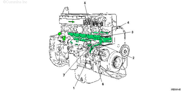
| Coolant System – STC Engines |
- Water pump coolant inlet
- Coolant to lower manifold cavity
- Coolant to cylinder liner block cavity
- Coolant to cylinder head
- Coolant to upper manifold cavity
- Lower manifold coolant to oil cooler
- Oil cooler to upper manifold cavity.
|
|
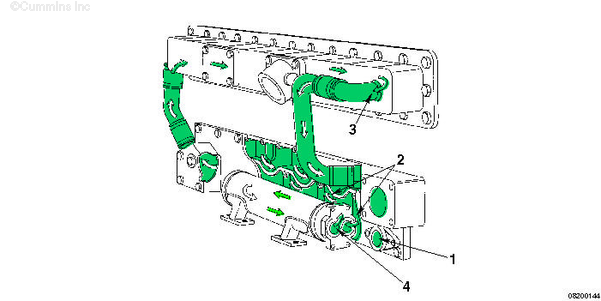
| Oil Cooler and Aftercooler Coolant – STC Engines |
- Coolant entry to lower manifold cavity
- Lower manifold coolants to oil cooler and aftercooler
- Aftercooler coolant outlet to upper manifold cavity
- Oil cooler water outlet to upper manifold.
|
|
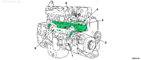
| Coolant System – CELECT™ Plus Engines |
- Water pump coolant inlet
- Coolant to lower manifold cavity
- Coolant to cylinder liner block cavity
- Coolant to cylinder head
- Coolant to upper manifold cavity
- Lower manifold coolant to oil cooler.
|
|
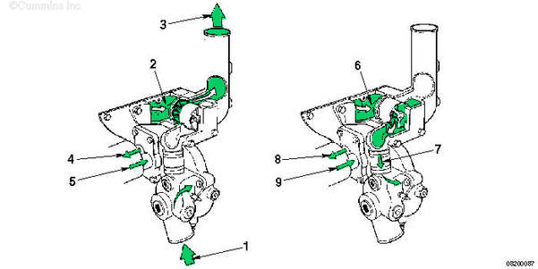
| Thermostat – STC and CELECT™ Plus Engines |
Open Thermostat — Items 1 to 5
Closed Thermostat — Items 6 to 9
- Water pump coolant inlet
- Upper manifold cavity (coolant to thermostat)
- Coolant outlet
- Lower manifold cavity to cooler
- Cooler to upper manifold cavity (before thermostat).
- Upper manifold cavity (coolant to thermostat)
- Coolant bypass (return to water pump)
- Lower manifold cavity to cooler
- Cooler to upper manifold cavity (before thermostat).
|
Last Modified: 01-Mar-2006
Published by Jack
Hello, I'm Jack, a diesel engine fan and a blogger. I write about how to fix and improve diesel engines, from cars to trucks to generators. I also review the newest models and innovations in the diesel market. If you are interested in learning more about diesel engines, check out my blog and leave your feedback.
View all posts by Jack
;)
;)
;)
;)
;)
;)
;)
;)