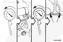
If the compression is low on one or more nonadjacent cylinders and the pressure can not be increased by oiling the rings, poor valve sealing is to be suspected.
Fuel is flammable. Keep all cigarettes, flames, pilot lights, arcing equipment, and switches out of the work area and areas sharing ventilation to reduce the possibility of severe personal injury or death when working on the fuel system.
Turn off the vehicle’s main fuel shutoff valve.
WARNING
Batteries can emit explosive gases. To reduce the possibility of personal injury, always ventilate the compartment before servicing the batteries. To reduce the possibility of arcing, remove the negative (-) battery cable first and attach the negative (-) battery cable last.
Disconnect the battery cables, negative (-) cable first.
WARNING
Coolant is toxic. Keep away from children and pets. If not reused, dispose of in accordance with local environmental regulations.
WARNING
Do not remove the pressure cap from a hot engine. Wait until the coolant temperature is below 50°C [120°F] before removing the pressure cap. Heated coolant spray or steam can cause personal injury.
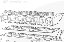
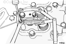
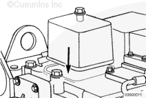
Remove the cylinder head. Refer to Procedure 002-004.
The following disassembly and assembly procedures are provided for inspection purposes only. Refer to the Shop Manual, Bulletin 3810206, for complete rebuild instructions.
Do not mix gasoline, alcohol, or gasohol with diesel fuel. This mixture can cause an explosion.
WARNING
When using solvents, acids, or alkaline materials for cleaning, follow the manufacturer’s recommendations for use. Wear goggles and protective clothing to reduce the possibility of personal injury.
WARNING
Use skin and eye protection when handling caustic solutions to reduce the possibility of personal injury.
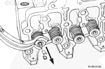
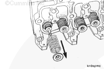
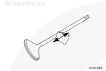
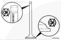
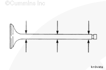
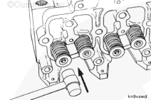
Polish the valve stem with a Scotch-Brite™ pad, or equivalent cleaning pad, and diesel fuel or solvent.
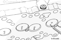
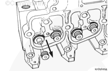
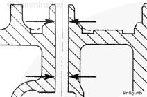
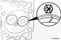
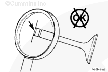
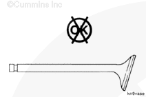
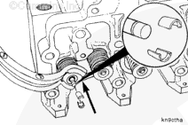
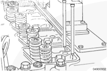
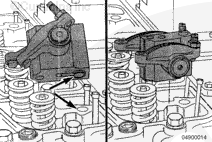
Inspect the valve seats for cracks or burned spots.
Refer to the following reuse guidelines for any cracks discovered. Service valve seats are available for seats with burned spots that will require more than 0.254 mm [0.010 in] of grinding to clean up. Refer to the Alternative Repair Manual, Bulletin 3666109, for valve seat installation procedures.
Hello, I'm Jack, a diesel engine fan and a blogger. I write about how to fix and improve diesel engines, from cars to trucks to generators. I also review the newest models and innovations in the diesel market. If you are interested in learning more about diesel engines, check out my blog and leave your feedback.
View all posts by Jack

 WARNING


;)
;)
;)
;)
;)
;)
;)
;)
;)
;)
;)
;)
;)
;)
;)
;)
;)
;)
;)
;)
;)
;)
;)
;)
;)
;)
;)
;)
;)
;)
;)
;)
;)
;)
;)
;)
;)
;)
;)
;)
;)
;)
;)
;)
;)
;)
;)
;)
;)
;)
;)
;)
;)
;)
;)
;)
;)
;)