|
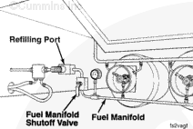
From the fuel manifold, the liquid fuel travels to the Cummins-supplied evaporator. Engine coolant is used to heat the liquid, vaporizing it to a gas. The gas is regulated at 172 kPa [25 psi] and then supplied to the engine fuel system.
Fuel System Gas Flow – Natural Gas
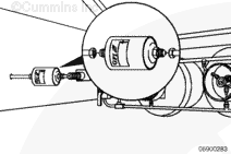
The reduced high-pressure gas, supplied from the OEM high-pressure regulator, is plumbed through a remote-mounted gas fuel filter. This filter is a coalescent type of filter that will capture oil contaminants and moisture typically found in compressed natural gas.
The gas will enter the fuel control housing inlet and pass through the low-pressure regulator that reduces the pressure of the natural gas to approximately 50 psig.
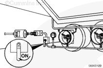
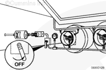
From the regulator, the gas will flow through the fuel shutoff valve. The fuel shutoff valve is normally closed until power (at least 9.5 VDC) is supplied by the electronic control module. The valve will not open until the ECM detects engine speed.
The gas will now pass through a screen pack, or flow straightener, to reduce the turbulent gas flow from the fuel shutoff valve. This screen pack is positioned directly above the fuel shutoff valve. The gas flow will proceed directly to a second screen pack located in the gas mass flow sensor assembly. This screen pack further reduces gas flow turbulence to provide optimum gas flow past the gas mass flow sensor.
Fuel System Gas Flow – Liquefied Petroleum Gas
The liquefied petroleum gas (35 to 250 psig, depending on temperature) is plumbed through an OEM-supplied in-line filter. The filter is a 5-micron magnetic-type. This filter will capture any contaminants that could be suspended in the liquid.
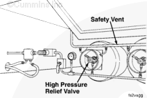
The liquefied petroleum gas enters the evaporator. The evaporator has an integral fuel shutoff valve, high-pressure relief valve, and pressure regulator. The fuel shutoff valve is normally closed until power (at least 9.5 VDC) is supplied from the ECM. The valve will not open until the ECM detects engine speed. Using engine coolant as the source of heat, the fuel is vaporized to a gas.
The gas (regulated between 19 and 30 psig) flows into the engine-mounted fuel filter housing. This filter is a coalescent type that will capture oil contaminants and moisture.
The gas will now pass through a screen pack, or flow straightener, to reduce the turbulent gas flow as it enters the gas housing. The gas flow will proceed directly through a second screen pack located in the gas mass flow sensor assembly. This screen pack further reduces gas flow turbulence to provide optimum gas flow past the gas mass flow sensor.
Natural Gas and Liquefied Petroleum Gas
The gas flow will leave the fuel control housing assembly by flowing through the fuel jumper hose to the mixer inlet. From the fuel inlet to air/fuel mixer the gas will be metered through the fuel control valve at the correct flow rate, depending on engine requirements and ECM controls. The metered fuel will then be induced into the intake airflow and be combined into an air/fuel mixture.
The air/fuel mixture will then be delivered to the engine’s intake manifold by the mechanical throttle plate or the idle control valve if the throttle plate is closed as in idling or motoring. The idle control valve is used instead of a governor to control idle speed. The idle speed of the engine is typically set at 800 rpm by using the INSITE™ service tool. Refer to the INSITE™ B5.9G User’s Manual, Part Number 3885798, for idle rpm adjustments. When the engine coolant temperature is below 15.5°C [60°F], the engine will idle at 1000 rpm. When the engine coolant temperature is above 15.5°C [60°F], the idle speed will return to 800 rpm or the customer-set idle speed.
Cold Starting
No cold-starting aids that would be introduced through the air system of the engine can be used. Aids such as block coolant heaters and oil pan immersion heaters are recommended for cold weather operation.
A warm-up cycle occurs when engine block coolant temperature is less than 15.5°C [60°F]. Idle speed will be 1000 rpm until engine block coolant temperature reaches 15.5°C [60°F].
The B5.9LPG will start unaided in cold weather at a minimum of -29°C [-20°F]. Care should be taken to allow the engine to idle for a time period to allow oil to flow through the engine and turbocharger. For rated power operation below -12°C [10°F], a means of increasing the available fuel supply pressure must be provided, such as placing a pump in the propane tank(s). This is to provide the minimum 241 kPa [35 psi] of fuel pressure required by the engine at all conditions and temperatures.
|
 WARNING
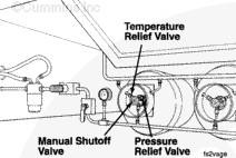
;)
;)
;)
;)
;)
;)
;)
;)
;)
;)
;)
;)
;)
;)