Centinel System – Master Repair Manual – 007-088   Centinel™ Oil Lines

Preparatory Steps

TOC

 WARNING 

Some state and federal agencies have determined that used engine oil can be carcinogenic and cause reproductive toxicity. Avoid inhalation of vapors, ingestion, and prolonged contact with used engine oil. If not reused, dispose of in accordance with local environmental regulations.
 WARNING 

To reduce the possibility of personal injury, avoid direct contact of hot oil with your skin.

Drain the Centinel™ system make-up oil tank.

NOTE: This oil is clean. Drain the oil into a container suitable enough to allow for reuse of the oil.

 
SMALL | MEDIUM | LARGE

Remove

TOC

L10 and M11 Engines


Remove the tie wraps used to secure the hoses. Tag and mark the hoses as they are removed. Note their location.

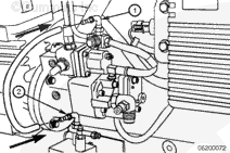
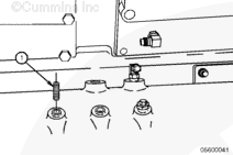
Remove the number 4 face sealing o-ring 90-degree elbow (1) at the fuel return tee fitting.

Remove the 90-degree elbow at the burn solenoid to remove the hose.

SMALL | MEDIUM | LARGE


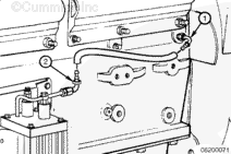
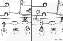
Remove the number 4 face sealing o-ring 90-degree elbow (1) at the oil rifle.

Remove the 90-degree elbow at the make-up solenoid to remove the hose.

SMALL | MEDIUM | LARGE


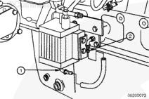
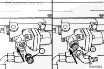
Remove the number 6 face sealing o-ring 90-degree elbow (1) located on the bottom of the oil control valve.

Remove the number 6 face sealing o-ring 90-degree elbow (2) from the 1/8 NPT adapter in the handhole cover.

SMALL | MEDIUM | LARGE
   

Burn-Only, ISM Engines


NOTE: It will probably be necessary to remove the starter on engines with low mounted ECMs to access this port.

Remove the tie wraps used to secure the hoses. Tag and mark the hoses as they are removed. Note their location.

Remove the oil rifle supply hose (5) from the 9/16-18 straight-thread o-ring male union (6) in the engine block oil rifle.

Remove the oil burn hose (1) from the 1/8-27 NPTF connector (2) in the fuel drain tee.

SMALL | MEDIUM | LARGE
   

Burn With Make-Up, ISM Engines


Remove the tie wraps used to secure the hoses. Tag and mark the hoses as they are removed. Note their location.

Remove the oil supply hose (2) from the control valve to the fuel drain tee.

SMALL | MEDIUM | LARGE


Remove the oil rifle supply hose (2) from the oil rifle fitting to the control valve (4).

Remove the oil replenishment hose (8) from the control valve (4) to the handhole cover (6).

SMALL | MEDIUM | LARGE


Remove the oil rifle fitting (1) in the engine block oil rifle port
(9/16-18 SAE o-ring), located just up and to the right, facing the control valve.

NOTE: It will probably be necessary to remove the starter on engines with low mounted ECMs to access this port.

Remove the clean oil fitting (7) from the hand hole cover.

SMALL | MEDIUM | LARGE
   

Burn With Make-Up, N14 Engines


NOTE: The following steps apply to N14 engines with a turbocharger-side mounted starter.

Remove the tie wraps used to secure the hoses. Tag and mark the hoses as they are removed. Note their location.

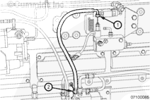
Loosen the elbow fittings at the block and oil control valve, and remove the number 4 hose line (2).

SMALL | MEDIUM | LARGE


Remove the number 4 hose fitting at the check valve and at the oil control valve solenoid.

SMALL | MEDIUM | LARGE


NOTE: The following steps apply to N14 engines with a fuel pump-side mounted starter.

Remove the number 4 hose line from the block and oil control valve.

SMALL | MEDIUM | LARGE


Remove the number 4 hose line at the check valve and at the oil control valve solenoid.

SMALL | MEDIUM | LARGE


Remove the fitting from the oil rifle.

SMALL | MEDIUM | LARGE
   

PT or STC


Centinel™ Fuel Pressure Line without Check Valve

Remove the tie wraps used to secure the hoses. Tag and mark the hoses as they are removed. Note their location.

Remove the number 4 hose line at the fuel junction block and fuel connecting block.

SMALL | MEDIUM | LARGE


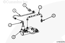
Centinel™ Fuel Pressure Sensor Line with Check Valve

Remove the tie wraps used to secure the hoses. Tag and mark the hoses as they are removed. Note their location.

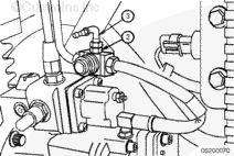
Loosen the fittings at the fuel drain and oil control valve and remove the number 4 hose line (3) .

SMALL | MEDIUM | LARGE
   

N14 Engines


Remove the tie wraps used to secure the hoses. Tag and mark the hoses as they are removed. Note their location.

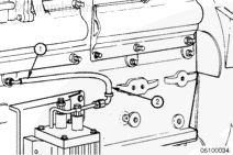
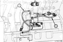
Remove the hose from the burn solenoid (2) and the fuel return line.

SMALL | MEDIUM | LARGE


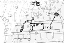
Remove the hose at the oil rifle (1) and the make-up solenoid.

Remove the hose.

SMALL | MEDIUM | LARGE


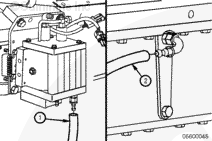
Remove the clean oil hose from the bottom of the Centinel™ valve and the engine block.

SMALL | MEDIUM | LARGE
   

ISX Engines


Remove the tie wraps used to secure the hoses. Tag and mark the hoses as they are removed. Note their location.

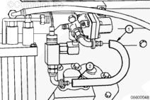
Loosen the hose clamp (1) on the control valve end of the hose, and remove the hose from the oil control valve make-up oil supply tube connector.

SMALL | MEDIUM | LARGE


Disconnect the oil rifle supply hose (1) from the control valve to the oil rifle check valve connector.

SMALL | MEDIUM | LARGE


Remove the make-up line (2) from the valve and male connector in the dipstick port.

SMALL | MEDIUM | LARGE


Disconnect the vehicle’s fuel drain line (1) to the T-connector.

Disconnect the oil burn line from the control valve to the T-connector.

SMALL | MEDIUM | LARGE
   

K19 Engines


Remove the tie wraps used to secure the hoses. Tag and mark the hoses as they are removed. Note their location.

Remove the fuel pressure hose from the fuel connecting block and the fuel rail tee.

SMALL | MEDIUM | LARGE


Remove the used oil burn hose from the burn solenoid and the fuel return tee fitting.

SMALL | MEDIUM | LARGE


Remove the used oil supply hose from the oil filter head and the oil bypass tube on the Centinel™ valve.

SMALL | MEDIUM | LARGE


Remove the clean oil replenishment hose from the oil pan fitting and the bottom of the Centinel™ valve.

SMALL | MEDIUM | LARGE
   

K38 and K50 Engines


Remove the tie wraps used to secure the hoses. Tag and mark the hoses as they are removed. Note their location.

Remove the fuel pressure hose from the fuel solenoid and the fuel connecting block.

SMALL | MEDIUM | LARGE


Remove the hose going from the bottom of the Centinel™ valve to the oil pan.

SMALL | MEDIUM | LARGE
   

Burn-Only, QSK45 and QSK60 Engines


Remove the tie wraps used to secure the hoses. Tag and mark the hoses as they are removed. Note their location.

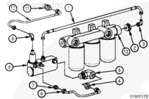
Remove the oil supply hose (10) from the fitting in the front gear cover to the top of the control valve (8).

Remove the 457-mm [18.0-in] oil burn hose (1) from the top of the control valve (8) to the inlet side of the fuel filter head (12).

Remove the 167-mm [6.8-in] bypass hose (6) from the burn port of the oil control valve to the inlet side of the control valve.

SMALL | MEDIUM | LARGE
   

Burn With Make-Up, QSK45 and QSK60 Engines


Remove the tie wraps used to secure the hoses. Tag and mark the hoses as they are removed. Note their location.

Remove the 389-mm [15.3-in] oil burn hose (6) from the control valve
(8) to the inlet side of fuel filter head (12).

SMALL | MEDIUM | LARGE


Remove the oil supply hose (10) from the oil check valve in the front gear cover to the top of the control valve (8).

Remove the 308-mm [12.1-in] oil replenishment hose (2) from the control valve (8) to the male elbow (9) in the handhole cover.

SMALL | MEDIUM | LARGE
   

Install

TOC

General Information


 WARNING 

Hoses must not be routed near excessively hot components and must be securely fastened to ensure they do not contact hot or moving components during any operating conditions. If routing near hot components cannot be avoided, then a fire sleeve around the hose must be used. All hoses must be adequately protected from chafe and fastened to appropriate structure, such that there is no overhung load on connections.
 CAUTION 

Before installing each number 4 and number 6 hose, slide protective hose covering over the hose. Failure to do so can cause chafing and lead to hose leakage.
 CAUTION 

When installing each number 4 and number 6 hose, make certain that it slides all the way over the barbs and mates up to the cap on the fitting. Failure to do so can lead to fitting failure, hose failure or both.

NOTE: Marine applications require that all hoses and fittings comply to SAE standards J1942 and J1527. Not all hoses and fittings supplied in the Centinel™ kits comply with these SAE standards. A metal make-up tank can also be required for Marine applications.

NOTE: Use engine lubricating oil to lubricate inside each end of the hoses for easier installation.

Before making final connections on any of the hoses for the Centinel™
plumbing, position the hoses and make certain there are no twists or kinks. Also, remember that the hoses must be as short as possible.

All p-clamps and tie wraps must be installed after completion of the complete assembly. When securing the hoses and wiring, be sure to keep them away from possible heat sources that can cause premature cracking or wear.

If installing a new system or disconnecting clean oil lines on a make-up system, the system must be primed before the engine is returned to service. Refer to Procedure 007-089 for the priming procedure.

SMALL | MEDIUM | LARGE
   

L10 and M11 Engines


NOTE: It will probably be necessary to remove the ECM to access the recommended oil rifle ports. However, on short-nosed conventional trucks, it is very difficult and time consuming to do this because of interference with the cab and frame rail. It is suggested that the first alternative oil supply location is to choose one of the two oil supply plugs located on the accessory drive. If this location is chosen, it will be necessary to order a number 4 face sealing o-ring x 1/4 NPT or number 4 face sealing o-ring x 9/16-18 straight-thread o-ring to accommodate the number 4 face sealing o-ring, 90-degree elbow. As a last choice, the oil supply on the oil filter head, which is usually used for the oil supply to the compression brakes, is an option. However, if you choose this location, you must use a wire-braided oil supply line because this location is on the hot side of the engine (turbocharger and exhaust manifold).

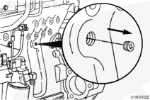
Remove the oil rifle plug on the starter side of the engine block.

SMALL | MEDIUM | LARGE


Install a 1/4 NPT (not shown) or 9/16-18 straight-thread o-ring adapter into the oil rifle port.

1/4 NPT 34 n.m [25 ft-lb]
9/16-18 Straight-Thread O-Ring 25 n.m [221 in-lb]

SMALL | MEDIUM | LARGE


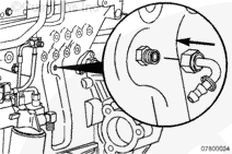
Install a number 4 face sealing o-ring 90-degree elbow onto the 9/16-18 straight-thread o-ring or 1/4 NPT (not shown) adapter that was just installed in the oil rifle port.

Torque Value:  14  n.m  [124 in-lb]

SMALL | MEDIUM | LARGE


Remove the fuel return line branch tee from the engine.

SMALL | MEDIUM | LARGE


Find the new in-line tee fitting that is provided in the upfit kit.

Install and tighten the following into the new tee:

  1. 1/8-27 NPT plug
Torque Value:  20  n.m  [177 in-lb]
  1. 1/8-27 NPT adapter
Torque Value:  20  n.m  [177 in-lb]
  1. number 4 face sealing o-ring 90-degree elbow.
Torque Value:  14  n.m  [124 in-lb]

SMALL | MEDIUM | LARGE


NOTE: When installing Centinel™ on M11 engines produced January 19, 1998, and later (ESN first 34896714), the fuel return tee included in the kit will not be compatible with the one supplied on the engine. A new part (Part Number 3099764, elbow, tube Connector) is available to use in these situations.

SMALL | MEDIUM | LARGE


Install the branch tee into the fuel return line.

SMALL | MEDIUM | LARGE


NOTE: Before making final connections on any hoses for the Centinel™
plumbing, position the hoses to make sure that there are no twists or kinks. Also, remember that the hoses should be as short as possible, and installed so that they do not come in contact with moving parts or rub other components.

SMALL | MEDIUM | LARGE


 CAUTION 

Before installing each number 4 or number 6 hose, slide hose covering onto the hose. Failure to do so can cause chafing and lead to hose leakage.
 CAUTION 

When installing each number 4 or number 6 hose, make sure that it slides all the way over the barbs and mates up to the cap on the fitting. Failure to do so can lead to fitting or hose failure.

SMALL | MEDIUM | LARGE


NOTE: When installing the hose onto the fittings, lubricate the inside of the hose with clean engine oil to help in installation.

Locate the number 6 hose in the kit.

Install the number 6 face sealing o-ring 90-degree elbow (1) on the bottom of the oil control valve.

Torque Value:  16  n.m  [142 in-lb]

Install the hose on the number 6 face sealing o-ring 90-degree elbow
(1) located on the bottom of the oil control valve.

Install the number 6 face sealing o-ring 90-degree elbow (2) on the 1/8 NPT adapter in the handhole cover.

Torque Value:  25  n.m  [221 in-lb]

Slide the hose covering onto the hose.

Route the hose to the number 6 face sealing o-ring 90-degree elbow that was installed onto the handhole cover, and cut the hose to fit.

Install the hose.

Secure the hose using tie wraps, if necessary.

SMALL | MEDIUM | LARGE


Locate the number 4 hose in the kit.

Install the hose on the number 4 face sealing o-ring 90-degree elbow
(1) at the oil rifle.

Slide the hose covering onto the hose.

Install the number 4 face sealing o-ring 90-degree elbow (2) at the end of the bypass tube located on the top of the oil control valve.

Torque Value:  16  n.m  [142 in-lb]

Route the hose to the number 4 face sealing o-ring 90-degree elbow (2)
at the end of the bypass tube located on the top of the valve, and cut the hose to fit.

Install the hose.

Secure the hose using tie wraps, if necessary.

SMALL | MEDIUM | LARGE


Install the hose on the number 4 face sealing o-ring 90-degree elbow
(1) at the fuel return tee fitting.

Slide the hose covering onto the hose.

Install the number 4 face sealing o-ring 90-degree elbow (1) on the burn solenoid.

Torque Value:  16  n.m  [142 in-lb]

Route the hose to the number 4 face sealing o-ring 90-degree elbow (2)
at the burn solenoid, and cut the hose to fit.

Install the hose.

Secure the hose using tie wraps, if necessary.

SMALL | MEDIUM | LARGE
   

Burn-Only, ISM Engines


Install the 9/16-18 straight-thread o-ring male union (6) in the engine block oil rifle port, located just up and to the right, facing the control valve.

Torque Value:  36  n.m  [27 ft-lb]

NOTE: It will probably be necessary to remove the starter on engines with low mounted ECMs to access this port.

SMALL | MEDIUM | LARGE


NOTE: On some factory installations, the 6-pin harness connector will be located behind the ECM. Pull down the connector while the starter is removed.

Install the 1/8-27 NPTF male connector (2) into the fuel drain tee.

Torque Value:  10  n.m  [89 in-lb]

If necessary, remove the factory-supplied fuel drain tee connector (if there is no 1/8-inch tap and plug in the factory-supplied connector) and install the fuel drain tee supplied in the kit.

Torque Value:  47  n.m  [35 ft-lb]

Reconnect the vehicle’s fuel drain line.

SMALL | MEDIUM | LARGE


Connect the oil rifle supply hose (5) to the 9/16-18 straight-thread o-ring male union (6) in the engine block oil rifle. Tighten the hose connector.

Torque Value:  16  n.m  [142 in-lb]

Install and tighten the oil burn hose (1) to the 1/8-27 NPTF connector
(2) in the fuel drain tee. Orient the hose to avoid unnecessary kinks. Tighten both hose connectors.

Torque Value:  16  n.m  [142 in-lb]

Using provided tie wraps, secure the hoses as necessary to avoid chafing and interference.

SMALL | MEDIUM | LARGE
   

Burn With Make-Up, ISM Engines


Install the oil rifle fitting (1) in the engine block oil rifle port
(9/16-18 SAE o-ring), located just up and to the right, facing the control valve.

NOTE: It will probably be necessary to remove the ECM to access this port on engine with low mounted ECMs.

Torque Value:  36  n.m  [27 ft-lb]

SMALL | MEDIUM | LARGE


Install the 1/8-27 NPTF male connector (2) into the fuel drain tee.

Torque Value:  10  n.m  [89 in-lb]

If necessary, remove the factory-supplied fuel drain tee connector (if there is no 1/8-inch tap and plug in the factory-supplied connector) and install the fuel drain tee supplied in the kit.

Torque Value:  47  n.m  [35 ft-lb]

Reconnect the vehicle’s fuel drain line.

SMALL | MEDIUM | LARGE


Install the 3/8-24 straight-thread o-ring male union (3) into the handhole cover (4) supplied in the kit.

Torque Value:  16  n.m  [142 in-lb]

SMALL | MEDIUM | LARGE


Install the handhole cover and gasket supplied in the kit using the four capscrews supplied. For a factory-supplied handhole cover-mounted fuel filter bracket, two of the capscrews and the two capscrews and spring washers are inserted through the fuel filter bracket and cover.

Tighten all four capscrews.

Torque Value:  47  n.m  [35 ft-lb]

SMALL | MEDIUM | LARGE


Connect the oil rifle supply hose (5) from the oil rifle fitting to the control valve.

Torque Value:  16  n.m  [142 in-lb]

Secure the hose to the block using the provided p-clip and the 25 mm captive washer capscrew.

Torque Value:  45  n.m  [35 ft-lb]

Connect the oil replenishment hose (7) from the control valve to the handhole cover (4).

Torque Value:  16  n.m  [142 in-lb]

SMALL | MEDIUM | LARGE


Install and tighten the oil burn hose (8) from the control valve to the fuel drain tee.

Torque Value:  16  n.m  [142 in-lb]

Using provided tie wraps, secure the hoses as necessary to avoid chafing and interference.

SMALL | MEDIUM | LARGE
   

PT or STC


NOTE: The following steps apply to Turbocharger-Side Mounted Starter, N14 with PT® or STC engines.

NOTE: The oil rifle contains three 1/8-inch pipe plugs and two 9/16-inch o-ring plugs.

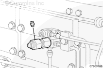
Choose the most convenient location to install the check valve. Remove the 1/8-inch pipe plug from the oil rifle.

NOTE: The location show in the accompanying illustration is the used engine oil supply port to the oil control valve.

SMALL | MEDIUM | LARGE


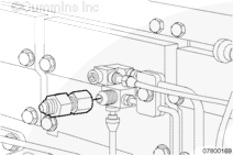
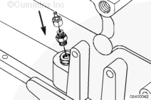
Install the check valve into the oil rifle. The check valve is a 1/8-inch NPTF to number 6 face sealing o-ring fitting.

Torque Value:  34  n.m  [25 ft-lb]

SMALL | MEDIUM | LARGE


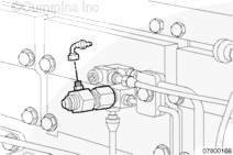
Loosely attach the number 4 face sealing o-ring to the number 4 hose elbow coupling to the check valve.

SMALL | MEDIUM | LARGE


Measure the distance between the number 4 hose elbow coupling at the check valve (2) and the straight push lock hose fitting (1) at the oil control valve solenoid using the number 4 hose. Cut the hose to length.

Cut a piece of hose cover to match the number 4 hose length. Slide the hose cover over the hose.

Remove the loosely attached hose elbow coupling from the check valve and place it in a vise. Lubricate both the hose and the barbed end of the elbow with clean oil. Push the number 4 hose completely onto the elbow.

Repeat the previous step with the straight push lock hose fitting that is loosely attached to the control valve solenoid.

Install the number 4 hose line and tighten the elbow fitting at the check valve and the straight push lock hose fitting at the oil control valve solenoid.

Torque Value:  14  n.m  [124 in-lb]

SMALL | MEDIUM | LARGE


NOTE: If the starter is not on the turbocharger side of the engine, refer to Fuel Pump-Side Mounted Starter, N14 with PT® or STC.

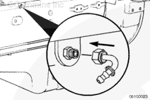
Remove the 9/16-18 straight thread o-ring plug from the cylinder block. The fresh oil replenishment line to the oil pan will be attached to this location.

SMALL | MEDIUM | LARGE


Install the 9/16-18 straight thread o-ring to the number 4 face sealing o-ring and tighten.

Torque Value:  20  n.m  [177 in-lb]

Loosely attach a number 4 hose elbow coupling to the number 4 face sealing o-ring fitting at the cylinder block.

SMALL | MEDIUM | LARGE


Measure the distance between the number 4 hose elbow couplings at the block and the top center of the oil control valve (fresh oil outlet location)
using the number 4 hose. Cut the hose to length.

Cut a piece of hose cover to match the number 4 hose length. Slide the hose cover over the hose.

Remove the loosely attached hose elbow couplings from the block and oil control valve.

Place each of the fittings in a vise. Lubricate both the hose and the barbed end of the elbow with clean oil. Push the number 4 hose completely onto each elbow.

Install the number 4 hose line (2), and tighten the elbow fittings at the block and oil control valve.

Torque Value:  14  n.m  [124 in-lb]

SMALL | MEDIUM | LARGE


NOTE: The following steps apply to Fuel Pump-Side Mounted Starter, N14 with PT® or STC engines.

NOTE: The oil rifle contains three 1/8-inch pipe plugs and two 9/16-inch o-ring plugs.

Choose the most convenient location to install the check valve. Remove the 1/8-inch pipe plug from the oil rifle.

NOTE: The location show in the accompanying illustration is the used engine oil supply port to the oil control valve.

SMALL | MEDIUM | LARGE


Install the check valve into the oil rifle. The check valve is a 1/8-inch NPTF to number 6 face sealing o-ring fitting.

Torque Value:  34  n.m  [25 ft-lb]

SMALL | MEDIUM | LARGE


Loosely attach the number 4 face sealing o-ring to the number 4 hose elbow coupling to the check valve.

SMALL | MEDIUM | LARGE


Measure the distance between the number 4 hose elbow coupling at the check valve (2) and the straight push lock hose fitting (1) at the oil control valve solenoid using the number 4 hose. Cut the hose to length.

Cut a piece of hose cover to match the number 4 hose length. Slide the hose cover over the hose.

Remove the loosely attached hose elbow coupling from the check valve and place it in a vise. Lubricate both the hose and the barbed end of the elbow with clean oil. Push the number 4 hose completely onto the elbow.

Repeat the previous step with the straight push lock hose fitting that is loosely attached to the control valve solenoid.

Install the number 4 hose line and tighten the elbow fitting at the check valve and the straight push lock hose fitting at the oil control valve solenoid.

Torque Value:  14  n.m  [124 in-lb]

SMALL | MEDIUM | LARGE


NOTE: If the starter is not on the turbocharger side of the engine, refer to Fuel Pump-Side Mounted Starter, N14 with PT® or STC.

Remove the 9/16-18 straight thread o-ring plug from the cylinder block. The fresh oil replenishment line to the oil pan will be attached to this location.

SMALL | MEDIUM | LARGE


Install the 9/16-18 straight thread o-ring to the number 4 face sealing o-ring and tighten.

Torque Value:  20  n.m  [177 in-lb]

Loosely attach a number 4 hose elbow coupling to the number 4 face sealing o-ring fitting at the cylinder block.

SMALL | MEDIUM | LARGE


NOTE: The cylinder block plug will probably be located behind the starter. If this is true, it will be necessary to use the other block plug that is commonly used for the STC oil drain. In this case, a “T” will be required to combine the STC oil drain line and Centinel™ replenishment line. The following steps outline the procedure.

Remove the STC oil drain line (1), and install the 9/16-18 straight thread o-ring to 1/4 NPTF female o-ring adapter.

Torque Value:  20  n.m  [177 in-lb]

SMALL | MEDIUM | LARGE


Install the street pipe tee (3) into the female o-ring adapter (4).

Torque Value:  26  n.m  [230 in-lb]

Install the 1/4 NPTF to number 4 face sealing o-ring fitting (2) into the street pipe tee.

Torque Value:  14  n.m  [124 in-lb]

Install the 5/8-18 x 45-degree flare to 1/4 NPTF fitting
(5) into the street pipe tee.

Torque Value:  20  n.m  [177 in-lb]

Install the STC oil drain line (1) to the flare fitting at the street pipe T-connection.

Torque Value:  30  n.m  [22 ft-lb]

Loosely attach a number 4 hose elbow coupling to the number face sealing o-ring fitting at the street pipe tee.

SMALL | MEDIUM | LARGE


Measure the distance between the number 4 hose elbow couplings at the street pipe tee and the top center of the oil control valve (fresh oil outlet location) using the number 4 hose. Cut the hose to length.

Cut a piece of hose cover to match the number 4 hose length. Slide the hose cover over the hose.

Remove the loosely attached hose elbow couplings from the street pipe tee and oil control valve.

Place each of the fittings in a vise. Lubricate both the hose and the barbed end of the elbow with clean oil. Push the number 4 hose completely onto each elbow.

Install the number 4 hose line, and tighten the elbow fittings at the block and oil control valve.

Torque Value:  14  n.m  [124 in-lb]

SMALL | MEDIUM | LARGE


Remove the fuel drain line from the engine drain line connector.

SMALL | MEDIUM | LARGE


Install the swivel hose adapter with the 1/8-inch NPTF tap onto the fuel drain line fitting.

Torque Value:  54  n.m  [40 ft-lb]

SMALL | MEDIUM | LARGE


Install the 1/8-27 to number 4 FSOR male connector to the swivel hose adapter.

Torque Value:  14  n.m  [124 in-lb]

SMALL | MEDIUM | LARGE


Loosely attach a number 4 FSOR straight hose coupling to the swivel hose adapter.

SMALL | MEDIUM | LARGE


Connect the fuel drain line to the swivel hose adapter.

Torque Value:  54  n.m  [40 ft-lb]

SMALL | MEDIUM | LARGE


Measure the distance between the fuel drain fitting and the number 4 hose fitting on the front face of the oil control valve (used engine oil outlet)
using the number 4 hose. Cut the hose to length.

Cut a piece of hose cover to match the number 4 hose length. Slide the hose cover over the hose.

Remove the loosely attached fittings from the fuel drain and oil control valve.

Place each of the fittings in a vise. Lubricate both the hose and the barbed end of the fitting with clean oil. Push the number 4 hose completely onto each fitting.

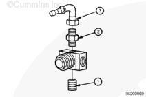
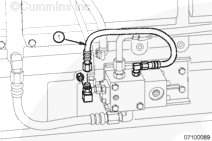
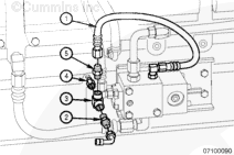
Install the number 4 hose line (3), and tighten the fittings at the fuel drain and oil control valve.

Torque Value:  14  n.m  [124 in-lb]

SMALL | MEDIUM | LARGE


Centinel™ Fuel Pressure Sensor Line with Check Valve

NOTE: If the fuel pressure line to the injectors has a check valve installed, the Centinel™ fuel pressure sensor line must be installed prior to the check valve.

If the fuel pressure line to the injectors has a check valve installed, install one of the 9/16-18 STOR to number 4 FSOR male union connectors (2)
to the fuel connecting block (3).

Torque Value:  34  n.m  [25 ft-lb]

Install either a straight or 90-degree elbow hose coupling (1) to the male union connector.

Torque Value:  14  n.m  [124 in-lb]

NOTE: Choose whichever fitting suits the application.

If the fuel pressure line to the injectors does not have a check valve installed, refer to the following procedure.

SMALL | MEDIUM | LARGE


Remove the STC fuel supply line (2), if equipped, from the fuel pressure line tee at the top of the fuel pump.

Remove the injector fuel pressure supply line (1) from the top of the fuel pump.

Remove the T-fitting (3) from the top of the fuel pump.

SMALL | MEDIUM | LARGE


Install the 1/8-inch pipe nipple (5) into the bottom of the female cross-fitting
(6). A vise will be needed to hold the female cross-fitting in place.

Torque Value:  14  n.m  [124 in-lb]

Install the 1/8 NPTF to female flare fitting (2) into the top of the female cross-fitting.

Torque Value:  14  n.m  [124 in-lb]

Install the 1/8 NPTF to number 4 FSOR fitting (1) into one arm of the female cross-fitting.

Torque Value:  14  n.m  [124 in-lb]

Install the 1/8 NPTF to 45-degree flare fitting (3) into the other arm of the female cross-fitting.

Torque Value:  14  n.m  [124 in-lb]

Tighten the STC fuel supply line (4) to the 45-degree flare fitting.

Torque Value:  30  n.m  [22 ft-lb]

Reconnect the injector fuel pressure line to the female flare fitting at the female cross-fitting.

Torque Value:  14  n.m  [124 in-lb]

SMALL | MEDIUM | LARGE


Loosely attach the number 4 hose elbow coupling to the number 4 FSOR fitting.

Measure the distance between the number 4 FSOR fitting at the fuel pump to the number 4 straight hose coupling at the fuel connecting block using the number 4 hose. Cut the hose to length.

Cut a piece of hose cover to match the number 4 hose length. Slide the hose cover over the hose.

Remove the loosely attached fittings at the fuel pump and fuel pressure sensor block.

Place each of the fittings in a vise. Lubricate both the hose and the barbed end of the fitting with clean oil. Push the number 4 hose completely onto each fitting.

Install the number 4 hose line, and tighten the fittings at the fuel pump and fuel pressure sensor block.

Torque Value:  14  n.m  [124 in-lb]

SMALL | MEDIUM | LARGE


Fuel Pressure Line without Check Valve

NOTE: Two junction blocks are located in the pressure line to the injectors
(one near the engine-side center and one near the engine rear prior to the pressure line entrance to the cylinder head). The STC fuel supply line, if equipped, is normally connected to the engine-side center junction block. However, the engine rear junction also is available if necessary.

If the fuel pressure line to the injectors does not have a check valve installed, remove the 1/8-inch pipe plug from the junction block.

Install a 1/8 NPTF to number 4 FSOR male connector into the pipe plug location on the junction block.

Loosely attach a number 4 hose elbow coupling to the number 4 FSOR fitting.

If the fuel pressure line to the injectors does have a check valve installed, refer to the previous procedure.

 
SMALL | MEDIUM | LARGE


Install one of the 9/16-18 STOR to number 4 FSOR male union connectors
(2) to the fuel connecting block (3).

Torque Value:  34  n.m  [25 ft-lb]

Install either a straight or 90-degree elbow hose coupling (1) to the male union connector.

Torque Value:  14  n.m  [124 in-lb]

NOTE: Choose whichever fitting suits the application.

SMALL | MEDIUM | LARGE


Measure the distance between the number 4 hose elbow couplings at the fuel connecting block on the Centinel™ mounting bracket and fuel junction block using the number 4 hose. Cut the hose to length.

Cut a piece of hose cover to match the number 4 hose length. Slide the hose cover over the hose.

Remove the loosely attached fittings at the fuel junction block and fuel connecting block.

Place each of the fittings in a vise. Lubricate both the hose and the barbed end of the elbow with clean oil. Push the number 4 hose completely onto each elbow.

Install the number 4 hose line, and tighten the fittings at the fuel junction block and fuel connecting block.

Torque Value:  14  n.m  [124 in-lb]

SMALL | MEDIUM | LARGE
   

N14 Engines


Remove the 9/16-18 o-ring plug from the fuel pump side of the engine.

SMALL | MEDIUM | LARGE


Install a 9/16-18 straight-thread o-ring adapter where the plug was removed.

Torque Value:  20  n.m  [177 in-lb]

Install a number 6 face sealing o-ring 90-degree elbow onto the 9/16-16 straight-thread o-ring adapter that was just installed.

Torque Value:  26  n.m  [230 in-lb]

SMALL | MEDIUM | LARGE


Remove the 9/16-18 oil rifle o-ring plug or 1/8-27 NPT plug (not shown) from the middle of the fuel pump side of the engine block.

NOTE: If this port is not available, locate an available port on the main oil rifle.

SMALL | MEDIUM | LARGE


Install a 9/16-18 straight-thread o-ring adapter or a 1/8 NPT adapter
(not shown) into the oil rifle port.

Torque Value:  20  n.m  [177 in-lb]

SMALL | MEDIUM | LARGE


Install a number 4 face sealing o-ring 90-degree elbow onto the 9/16-18 straight-thread o-ring adapter that was just installed in the oil rifle port.

Torque Value:  14  n.m  [124 in-lb]

SMALL | MEDIUM | LARGE


Remove the fuel return line branch tee from the engine.

SMALL | MEDIUM | LARGE


Using the new fuel return tee that was provided in the upfit kit, install the following:

  1. 1/8-27 NPT plug into the top of the tee
Torque Value:  20  n.m  [177 in-lb]
  1. 1/8-27 NPT adapter into the bottom of the tee
Torque Value:  20  n.m  [177 in-lb]
  1. number 4 face sealing o-ring straight fitting or a 90-degree elbow onto the 1/8-27 NPT adapter.
Torque Value:  14  n.m  [124 in-lb]

SMALL | MEDIUM | LARGE


NOTE: When installing Centinel™ on N14 engines produced January 29, 1998, and later (ESN first 11877641), the fuel return tee included in the kit will not be compatible with the one supplied on the engine. The new part (Part Number 3099992, elbow, tube connector) is available to use in these situations.

SMALL | MEDIUM | LARGE


Install the new fuel return branch tee into the fuel return line.

SMALL | MEDIUM | LARGE


NOTE: Before making final connections on any of the hoses for the Centinel™
plumbing, position the hoses to make sure there are no twists or kinks. Also, remember that the hoses should be as short as possible, and installed so that they do not come in contact with moving parts, rub other components, or come in contact with hot surfaces.

SMALL | MEDIUM | LARGE


 CAUTION 

Before installing each number 4 or number 6 hose, slide hose covering onto the hose. Failure to do so can cause chafing and lead to hose leakage.
 CAUTION 

When installing each number 4 or number 6 hose, make sure that it slides all the way over the barbs and mates up to the cap on the fitting. Failure to do so can lead to fitting or hose failure.

NOTE: When installing the hose onto the fittings, lubricate the inside of the hose with clean engine oil to help in installation.

SMALL | MEDIUM | LARGE


Locate the number 6 hose in the kit.

Slide the hose covering onto the hose.

Install the hose onto the number 6 face sealing o-ring 90-degree elbow
(1) located on the bottom of the oil control valve.

Route the hose to the number 6 face sealing o-ring 90-degree elbow (2)
installed in the left side of the engine, and cut the hose to fit.

Install the hose.

Secure the hose using tie wraps, if necessary.

SMALL | MEDIUM | LARGE


Locate the number 4 hose in the kit.

Slide the hose covering onto the hose.

Install the hose onto the number 4 face sealing o-ring 90-degree elbow at the oil rifle (1).

Route the hose to the number 4 90-degree face sealing o-ring elbow or face sealing o-ring straight fitting at the end of the bypass tube (2), located at the top of the valve, and cut the hose to fit.

Install the hose.

Secure the hose using tie wraps, as necessary.

SMALL | MEDIUM | LARGE


Locate the number 4 hose in the kit.

Slide the hose covering onto the hose.

Install onto the 90-degree face sealing o-ring elbow or face sealing o-ring straight fitting at the fuel return tee fitting (1).

Route the hose to the number 4 face sealing o-ring 90-degree elbow at burn solenoid (2), and cut the hose to fit.

Install the hose.

Secure the hose using tie wraps, as necessary.

SMALL | MEDIUM | LARGE
   

ISX Engines


Install the T-connector (2) to the integrated fuel system module fuel return and tighten.

Torque Value:  54  n.m  [40 ft-lb]

Connect the vehicle’s fuel drain line (1) to the T-connector and tighten.

Torque Value:  54  n.m  [40 ft-lb]

Connect the oil burn line from the control valve to the T-connector and tighten.

Torque Value:  47  n.m  [35 ft-lb]

SMALL | MEDIUM | LARGE


Install the M18 x 1.5 SAE o-ring male union (1) into the unused dipstick port and tighten.

Torque Value:  75  n.m  [55 ft-lb]

Install the make-up line (2) to the valve and male connector in the dipstick port.

Torque Value:  47  n.m  [35 ft-lb]

Use provided P-clip (3) and M10-1.5 x 16-mm capscrew (4)
to secure the hose (2) to avoid chafing and interference. Tighten the capscrew.

Torque Value:  47  n.m  [35 ft-lb]

SMALL | MEDIUM | LARGE


Connect the oil rifle supply hose (1) from the control valve to the oil rifle check valve connector. Position the check valve connector and hose to make certain that there is clearance between the hose and the intake manifold.

Tighten the connector.

Torque Value:  47  n.m  [35 ft-lb]

SMALL | MEDIUM | LARGE


Route the make-up tank hose (1) along the fram rail that is opposite the exhaust and forward to the 3/4-inch tube connector located on the back end of the oil control valve. Cut the hose to fit.

SMALL | MEDIUM | LARGE


NOTE: For easier installation, use clean engine oil to lubricate the end of the hose before installing the hose onto the drain fitting.

NOTE: When installing the make-up supply hose, verify that it is located and secured in such a way as to avoid chafing. If necessary, reroute the make-up supply hose.

Install a hose clamp (1) onto the control valve end of the hose, and install the hose onto the oil control valve make-up oil supply tube connector.

Slide the hose clamp into position over the fitting and tighten.

After installing the oil make-up tank oil level sensor wiring, use the provided tie wraps to secure the hose to the frame rail.

SMALL | MEDIUM | LARGE
   

K19 Engines


Remove the 3/4-inch plug from the left side of the oil pan.

SMALL | MEDIUM | LARGE


Locate the 1/4 NPT adapter in the upfit kit.

Install the reducer bushing and tighten.

Torque Value:  27  n.m  [239 in-lb]

Install a number 6 face sealing o-ring straight fitting onto the adapter just installed in the reducer.

Torque Value:  26  n.m  [230 in-lb]

SMALL | MEDIUM | LARGE


Remove the hose from the fuel return drain line.

SMALL | MEDIUM | LARGE


Install the swivel fitting, ST-434-1, onto the fuel drain fitting.

Torque Value:  54  n.m  [40 ft-lb]

SMALL | MEDIUM | LARGE


Install a 1/8-27 NPT adapter into the swivel fitting. Position the adapter on top of the swivel fitting.

Torque Value:  14  n.m  [124 in-lb]

SMALL | MEDIUM | LARGE


Install a number 4 face sealing o-ring 90-degree elbow to the adapter that was just installed.

Torque Value:  14  n.m  [124 in-lb]

SMALL | MEDIUM | LARGE


Install the fuel return drain line hose that was removed back onto the swivel fitting.

Torque Value:  54  n.m  [40 ft-lb]

SMALL | MEDIUM | LARGE


NOTE: If the tee port is unavailable, use the 1/8 NPT plug available on the fuel pump shutoff solenoid.

Remove the plug from the fuel rail tee.

SMALL | MEDIUM | LARGE


Install a 1/8 NPT adapter where the plug was removed from the fuel rail tee or fuel pump shutoff solenoid.

Torque Value:  14  n.m  [124 in-lb]

Install a 90-degree face sealing o-ring elbow onto the tee fitting.

SMALL | MEDIUM | LARGE


NOTE: Remove the plug from the clean oil side of the filter head.

Remove the plug from the oil filter head on the left side of the engine.

SMALL | MEDIUM | LARGE


Install a 1/8-27 NPT adapter into the oil filter head where the plug was removed.

Torque Value:  14  n.m  [124 in-lb]

Install a number 4 face sealing o-ring straight fitting or 90-degree face sealing o-ring elbow (not shown) on the 1/8-27 NPT adapter.

Torque Value:  14  n.m  [124 in-lb]

SMALL | MEDIUM | LARGE


 CAUTION 

Before installing each number 4 and number 6 hose, slide protective hose covering over the hose. Failure to do so can cause chafing and lead to hose leakage.
 CAUTION 

When installing each number 4 and number 6 hose, make certain that it slides all the way over the barbs and mates up to the cap on the fitting. Failure to do so can lead to fitting/hose failure.

NOTE: Before making final connections on any of the hoses for the Centinel™
plumbing, position the hoses and make certain there are no twist or kinks. Also, remember that the hoses should be as short as possible.

NOTE: Use engine oil to lubricate inside each end of the hoses for easier installation.

NOTE: All p-clamps and tie wraps should be installed after completion of the complete assembly. When securing the hoses and wiring, be sure to keep them away from possible heat sources that can cause premature cracking or wear.

SMALL | MEDIUM | LARGE


Locate the number 6 hose in the kit.

Slide a protective hose covering onto the hose.

Install the hose (1) onto the number 6 face sealing o-ring 90-degree elbow or straight fitting located at the bottom of the valve.

NOTE: For burn-only, this will be a 90-degree fitting coming from the u-tube.

Route the hose (2) onto the number 6 straight fitting that was installed on the oil pan, and cut the hose to fit.

Install the hose.

Secure the hose using tie straps, if necessary.

SMALL | MEDIUM | LARGE


Locate the number 4 hose in the kit.

Slide a protective hose covering onto the hose.

Install the hose (A) on the number 4 straight fitting located on the oil filter head.

Route the hose (B) to the number 4 straight fitting at the end of the lubricating oil bypass located on top of the valve, and cut the hose to fit.

Install the hose on the fitting.

Secure the hose with p-clamps.

SMALL | MEDIUM | LARGE


Locate the number 4 hose in the kit.

Slide a protective hose covering onto the hose.

Install the hose (1) on the number 4 face sealing o-ring 90-degree elbow at the fuel return tee fitting.

Route the hose (2) to the number 4 face sealing o-ring 90-degree elbow at the burn solenoid, and cut the hose to fit.

Install the hose on the fitting.

Secure the hose using tie wraps, if necessary.

SMALL | MEDIUM | LARGE


Locate the number 4 hose in the kit.

Slide a protective hose covering onto the hose.

Install the hose on the number 4 face sealing o-ring 90-degree elbow at the fuel rail tee (1).

Route the hose to the number 4 face sealing o-ring 90-degree elbow at the fuel connecting block (2), and cut the hose to fit.

Install the hose on the fitting.

Secure the hose using tie wraps, if necessary.

SMALL | MEDIUM | LARGE
   

K38 and K50 Engines


Remove the 1/2-20 straight-thread plug from the left side of the oil pan.

SMALL | MEDIUM | LARGE


Locate 1/2-20 adapter from the upfit kit.

Cut off the o-ring.

Install a sealing washer to where the o-ring was just removed.

SMALL | MEDIUM | LARGE


Where the plug was removed from the oil pan, install the 1/2-20 adapter with a sealing washer.

Torque Value:  22  n.m  [195 in-lb]

Install a number 6 face sealing o-ring 90-degree elbow onto the reducer just installed in the oil pan.

Torque Value:  14  n.m  [124 in-lb]

SMALL | MEDIUM | LARGE


Remove the hose from the fuel return drain line.

SMALL | MEDIUM | LARGE


Install the swivel fitting onto the fuel drain fitting.

Torque Value:  54  n.m  [40 ft-lb]

SMALL | MEDIUM | LARGE


Install a 1/8-27 NPT adapter into the fitting. Position the adapter on top of the swivel fitting.

Torque Value:  14  n.m  [124 in-lb]

SMALL | MEDIUM | LARGE


Install a number 4 face sealing o-ring 90-degree elbow to the adapter.

Torque Value:  14  n.m  [124 in-lb]

SMALL | MEDIUM | LARGE


Install the fuel return line back onto the end of the swivel fitting.

Torque Value:  54  n.m  [40 ft-lb]

SMALL | MEDIUM | LARGE


NOTE: Remove the plug from the clean oil side of the filter head.

Remove the plug from the oil filter head on the left side of the engine
(1).

SMALL | MEDIUM | LARGE


Install a 1/4-18 NPT adapter into the oil filter head where the plug was removed.

Torque Value:  27  n.m  [239 in-lb]

Install a number 4 face sealing o-ring 90-degree elbow (1) onto the 9/16-18 adapter on the oil filter head.

Torque Value:  14  n.m  [124 in-lb]

SMALL | MEDIUM | LARGE


Remove the plug (1) from the fuel solenoid.

SMALL | MEDIUM | LARGE


Install a 1/2-20 or 1/4-18 NPT (1) (whichever is necessary) adapter from where the plug was removed from the fuel solenoid.

Torque Value:  20  n.m  [177 in-lb]

Install a number 4 face sealing o-ring 90-degree elbow onto the tee fitting (2).

Torque Value:  14  n.m  [124 in-lb]

SMALL | MEDIUM | LARGE


 CAUTION 

Before installing each number 4 and number 6 hose, slide protective hose covering over the hose. Failure to do so can cause chafing and lead to hose leakage.
 CAUTION 

When installing each number 4 and number 6 hose, make certain that it slides all the way over the barbs and mates up to the cap on the fitting. Failure to do so can lead to fitting/hose failure.

NOTE: Before making final connections on any of the hoses for the Centinel™
plumbing, position the hoses and make sure there are no twists or kinks. Also, remember that the hoses should be as short as possible.

NOTE: Use engine oil to lubricate inside each end of the hoses for easier installation.

NOTE: All p-clamps and tie wraps should be installed after completion of the complete assembly. When securing the hoses and wiring be, sure to keep them away from possible heat sources that can cause premature cracking or wear.

SMALL | MEDIUM | LARGE


Locate the number 6 hose in the kit.

Slide a protective hose covering onto the hose.

Install the hose (1) onto the number 6 face sealing o-ring straight fitting located at the bottom of the valve.

NOTE: For burn-only, this will be the tee coming off the u-tube.

Route the hose (2) onto the number 6 face sealing o-ring 90-degree elbow that was installed on the oil pan, and cut the hose to fit.

Install the hose.

Secure the hose using three of the supplied p-clamps along the oil pan rail.

SMALL | MEDIUM | LARGE


Locate the number 4 hose in the kit.

Slide the protective hose covering onto the hose.

Install the hose (1) on the number 4 face sealing o-ring 90-degree elbow located on the oil filter head.

Route the hose to the number 4 sealing o-ring straight fitting at the end of the lubricating oil bypass (2) located on top of the valve, and cut the hose to fit.

Install the hose on the fitting.

Secure the hose with p-clamps and tie wraps as necessary.

SMALL | MEDIUM | LARGE


Locate the number 4 hose in the kit.

Slide the protective covering over the hose.

Install the hose on the number 4 90-degree face sealing o-ring elbow at the fuel return swivel fitting (1).

Route the hose to the number 4 90-degree face sealing o-ring elbow at the burn solenoid (2), and cut the hose to fit.

Install the hose on the fitting.

Secure the hose using tie wraps, if necessary.

SMALL | MEDIUM | LARGE


Locate the number 4 hose in the kit.

Slide the protective covering over the hose.

Install the hose on the number 4 face sealing o-ring 90-degree elbow at the fuel solenoid.

Route the hose to the number 4 face sealing o-ring 90-degree elbow at the fuel connecting block, and cut the hose to fit.

Install the hose on the fitting.

Secure the hose using tie wraps, if necessary.

SMALL | MEDIUM | LARGE
   

Burn-Only, QSK45 and QSK60 Engines


Remove plug from inlet side of fuel filter head. Install the adapter
(2) into the open port in the fuel filter head (12).

Torque Value:  47  n.m  [35 ft-lb]

Install the male elbow (3) connector into the adapter (2) fitted to the inlet side of the fuel filter head (12).

Torque Value:  34  n.m  [25 ft-lb]

Install the check valve in the gear housing.

Torque Value:  34  n.m  [25 ft-lb]

Install and tighten the oil supply hose (10) from the oil check valve in the front gear cover to the top of the control valve (8).

Torque Value:  16  n.m  [142 in-lb]

Install and tighten the 457-mm [18.0-in] oil burn hose (1) from the top of the control valve (8) to the inlet side of the fuel filter head (12).

Torque Value:  16  n.m  [142 in-lb]

Install and tighten the 167-mm [6.8-in] bypass hose (6) from the burn port of the oil control valve to the inlet side of the control valve.

Torque Value:  16  n.m  [142 in-lb]

Using provided tie wraps, secure the hoses as necessary to avoid chafing and interference.

SMALL | MEDIUM | LARGE
   

Burn With Make-Up, QSK45 and QSK60 Engines


Remove plug from inlet side of fuel filter head. Install the adapter
(4) into the open port in the fuel filter head (12).

Torque Value:  47  n.m  [35 ft-lb]

SMALL | MEDIUM | LARGE


Install the oil rifle check valve (1) in the front gear cover port.

Torque Value:  36  n.m  [27 ft-lb]

SMALL | MEDIUM | LARGE


Install the male elbow (5) connector into the adapter (4) fitted to the inlet side of the fuel filter head (12).

Torque Value:  34  n.m  [25 ft-lb]

SMALL | MEDIUM | LARGE


Install the male elbow (9) into the handhole cover.

Torque Value:  16  n.m  [142 in-lb]

SMALL | MEDIUM | LARGE


Install and tighten the oil supply hose (10) from the oil check valve in the front gear cover to the top of the control valve (8).

Torque Value:  16  n.m  [142 in-lb]

Install and tighten the 308-mm [12.1-in] oil replenishment hose (2)
from the control valve (8) to the male elbow (9) in the handhole cover.

Torque Value:  16  n.m  [142 in-lb]

SMALL | MEDIUM | LARGE


Install and tighten the 389-mm [15.3-in] oil burn hose (6) from the control valve (8) to the inlet side of fuel filter head (12).

Torque Value:  16  n.m  [142 in-lb]

Using provided tie wraps, secure the hoses as necessary to avoid chafing and interference.

SMALL | MEDIUM | LARGE
Last Modified:  29-Apr-2004