Centinel System – Master Repair Manual – 019-131   Centinel™ Wiring Harness

Remove

TOC

 WARNING 

Batteries can emit explosive gases. To reduce the possibility of personal injury, always ventilate the compartment before beginning servicing the batteries. To reduce the possibility of arcing, remove the negative (-) battery cable first and attach the negative (-) battery cable last.

Disconnect the battery cables.

SMALL | MEDIUM | LARGE


Disconnect the wiring harness from the following:

  1. Burn solenoid
  2. Make-up solenoid
  3. Centinel™ control module
  4. Warning lamp assembly (high-horsepower only)
  5. Starter positive post
  6. Harness ground
  7. Datalink
  8. Make-up oil tank oil level sensor
  9. Fuel solenoid
  10. Fuel rail pressure sensor (high-horsepower only).

SMALL | MEDIUM | LARGE


Cut the ties holding the wiring harness.

Remove the engine harness.

SMALL | MEDIUM | LARGE
   

Install

TOC

Burn-Only, L and M Series Engines


It will be necessary to choose a location for mounting the heavy-duty Centinel™ control module. Location of the Centinel™ control module should provide visibility of the diagnostic lamps to operators and maintenance personnel.

Recommended locations include:

  • Inside the cab
  • On the frame rail
  • On the rear of the cab.

NOTE: Do not mount the Heavy-Duty Centinel™ control module
under the hood or in the engine compartment. The Centinel™ control module is not designed (or covered by warranty) for engine compartment temperatures.

 
SMALL | MEDIUM | LARGE


NOTE: Complete the installation of the wiring harness before using p-clamps or tie wraps to secure the wiring harness from rubbing.

Locate and remove the Centinel™ wiring harness from the package.

NOTE: When connecting the harness to the Centinel™ control module, verify that the connector locks are engaged.

Install the 12-pin connector to the Centinel™ control module.

SMALL | MEDIUM | LARGE


Locate the three oil monitoring plugs in the package. Only
one of the plugs will be installed, depending on the type of oil to be used in the engine.

  1. Standard oil monitoring plug – white wire
  2. Advanced oil monitor plug – black wire
  3. Service plug – red wire.

NOTE: The service plug is used to place the installed Centinel™ system into service and to reset the system after an oil change.

SMALL | MEDIUM | LARGE


Remove the cover from the oil monitoring plug on the Centinel™
wiring harness and install the appropriate calibration plug.

Install the appropriate calibration plug.

NOTE: Refer to Procedure 018-003 for engine specific blend rates.

SMALL | MEDIUM | LARGE


Route the Centinel™ wiring harness to the frame rail opposite the exhaust and forward to the oil control valve.

Secure the harness from rubbing using P-clamp and tie wraps.

SMALL | MEDIUM | LARGE


Locate the connector labeled BURN SOLENOID and connect it to the connector on the top of the oil control valve leading to the burn solenoid.

SMALL | MEDIUM | LARGE


Locate the connector labeled MAKE-UP SOLENOID and connect it to the connector on the top of the oil control valve leading to the make-up solenoid.

SMALL | MEDIUM | LARGE


NOTE: This step applies to engines equipped with the CELECT™ Plus system only. For non-CELECT™ Plus engines, continue to the next step.

Near the engine ECM, locate and remove the cover from the engine datalink connector.

Install the connector labeled DIAGNOSTIC LAMP ENGINE DATALINK CONNECTOR.

SMALL | MEDIUM | LARGE


Drill a 1/4-inch hole in a location on the firewall of the engine compartment.

Install the grommet provided in the kit and route the wires through it and into the cab.

SMALL | MEDIUM | LARGE


For engines that do not have a 6-pin datalink connector by the ECM, it is necessary to install two wires for the datalink inside the cab. These wires will be spliced into the J1587 datalink connector. These will be the same wires that are routed to the datalink, usually located under the dashboard. Locate the wires that lead to this connector and connect as specified in the following table:

Signal 8-Pin Connector 6-Pin Connector 2-Pin Connector
Datalink (+) Pin 1 Pin A Pin A
Datalink (-) Pin 2 Pin B Pin B

SMALL | MEDIUM | LARGE


Splice the wires using the above table as a reference (polarity).

Butt splices are designed to provide the best possible cold joint connection when properly crimped.

SMALL | MEDIUM | LARGE


 CAUTION 

Overheating of the butt splice can lead to wire damage.

Butt splices also provide protection against corrosion. After crimping the connection, heat the shrink tube with a heat gun until the shrink tube has sealed the joint.

SMALL | MEDIUM | LARGE


NOTE: It is very important that the Centinel™ system be properly grounded.

Locate the black lead (ground) on the Centinel™ wiring harness.

Connect the ground lead to ground on the starter (2).

Connect the red lead (positive) of the harness to the positive post
(1) of the starter solenoid.

SMALL | MEDIUM | LARGE


Connect the last remaining wire on the Centinel™ harness to the positive post on fuel shutoff solenoid.

NOTE: Inspect all the wiring and plumbing lines to make certain your connections and clamps are tight, and all components are secured from rubbing.

SMALL | MEDIUM | LARGE


On the Centinel™ wiring harness, locate the two wire connectors labeled LOW OIL LEVEL SENSOR. Cap the connector with the jumper harness found in the burn-only conversion kit.

NOTE: The burn-only Centinel™ system uses the same harness as the standard Centinel™ system. As the standard system uses a make-up oil tank with a low oil level switch/sensor, in the burn-only system this sensor pickup in the harness must be jumped (to simulate a tank with adequate make-up oil) for the Centinel™ control module to operate the system properly.

 
SMALL | MEDIUM | LARGE


NOTE: The Centinel™ wiring harness is about 20 feet long. Depending on where the Centinel™ control module or lamp box is located, there can be a considerable length of excess harness. This excess must
be rolled together and securely tie-wrapped out of the way.

 
SMALL | MEDIUM | LARGE
   

Burn With Make-Up, L and M Series Engines


NOTE: Complete the installation of the wiring harness before using p-clamps or tie wraps to secure the wiring harness from rubbing.

Locate and remove the Centinel™ wiring harness from the package.

NOTE: When connecting the harness to the Centinel™ control module, verify that the connector locks are engaged.

Install the 12-pin connector to the Centinel™ control module.

SMALL | MEDIUM | LARGE


Use p-clamps to secure the harness to the make-up oil tank.

SMALL | MEDIUM | LARGE


Locate the connection on the wiring harness labeled MAKE-UP TANK sensor and connect it to the make-up tank sensor.

SMALL | MEDIUM | LARGE


Locate the three oil calibration plugs in the package. Only
one of the plugs will be installed, depending on the type of oil to be used in the engine.

  1. Standard oil monitoring plug – white wire
  2. Advanced oil monitor plug – black wire
  3. Service plug – red wire.

NOTE: The service plug is used to place the installed Centinel™ system into service and to reset the system after an oil change.

SMALL | MEDIUM | LARGE


Remove the cover from the oil monitoring plug on the Centinel™
wiring harness and install the appropriate calibration plug.

NOTE: Refer to Procedure 018-003 for engine specific blend rates.

SMALL | MEDIUM | LARGE


Route the Centinel™ wiring harness to the frame rail opposite the exhaust and forward to the oil control valve.

Secure the harness from rubbing using P-clamp and tie wraps.

SMALL | MEDIUM | LARGE


Locate the connector labeled BURN SOLENOID and connect it to the connector on the top of the oil control valve leading to the burn solenoid.

SMALL | MEDIUM | LARGE


Locate the connector labeled MAKE-UP SOLENOID and connect it to the connector on the top of the oil control valve leading to the make-up solenoid.

SMALL | MEDIUM | LARGE


NOTE: This step applies to engines equipped with the CELECT™ Plus system only. For non-CELECT™ Plus engines, continue to the next step.

Near the engine ECM, locate and remove the cover from the engine datalink connector.

Install the connector labeled DIAGNOSTIC LAMP ENGINE DATALINK CONNECTOR.

SMALL | MEDIUM | LARGE


Drill a 1/4-inch hole in a location on the firewall of the engine compartment.

Install the grommet provided in the kit and route the wires through it into the cab.

SMALL | MEDIUM | LARGE


For engines that do not have a 6-pin datalink connector by the ECM, it is necessary to install two wires for the datalink inside the cab. These wires will be spliced into the J1587 datalink connector. These will be the same wires that are routed to the datalink, usually located under the dashboard. Locate the wires that lead to this connector and connect as specified in the following table:

Signal 8-Pin Connector 6-Pin Connector 2-Pin Connector
Datalink (+) Pin 1 Pin A Pin A
Datalink (-) Pin 2 Pin B Pin B

SMALL | MEDIUM | LARGE


Splice the wires using the above table as a reference (polarity).

Butt splices are designed to provide the best possible cold joint connection when properly crimped.

SMALL | MEDIUM | LARGE


 CAUTION 

Overheating of the butt splice can lead to wire damage.

Butt splices also provide protection against corrosion. After crimping the connection, heat the shrink tube with a heat gun until the shrink tube has sealed the joint.

SMALL | MEDIUM | LARGE


NOTE: It is very important that the Centinel™ system be properly grounded.

Locate the black lead (ground) on the Centinel™ wiring harness.

Connect the ground lead to ground on the starter (2).

Connect the red lead (positive) of the harness to the positive post
(1) of the starter solenoid.

SMALL | MEDIUM | LARGE


Connect the last remaining wire on the Centinel™ harness to the positive post on fuel shutoff solenoid.

NOTE: Inspect all the wiring and plumbing lines to make certain your connections and clamps are tight, and all components are secured from rubbing.

SMALL | MEDIUM | LARGE
   

Burn-Only, ISM Engines


Install the Centinel™ jumper harness between the engine harness
(6-pin connector) and the control valve solenoid (2-pin connector).

Verify that the connector locks are engaged.

NOTE: For burn-only, pins 24 and 25 of the 31-pin OEM connector must be jumped to simulate adequate oil is available in the make-up tank, even though there is no make-up tank.

Locate the jumper wiring harness in the burn-only valve and mounting or conversion kit.

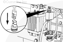
Locate the 31-pin OEM interface connector on the side of the engine block.

SMALL | MEDIUM | LARGE


Disconnect the 31-pin OEM connector. Locate pins 24 and 25 in the OEM interface connector, and remove the connector cavity plugs in the 24-
and 25-pin locations.

Install the two female sockets of the jumper harness (supplied in the kit) into pins 24 and 25.

NOTE: Make certain the sockets “snap” solidly into place.

Reconnect the OEM 31-pin connector, making absolutely certain the connector is solidly locked in place.

Use provided tie wraps to secure the remainder of the oil make-up level sensor leads to avoid chafing and to make sure no stress is applied to the pin sockets.

SMALL | MEDIUM | LARGE


Properly reinstall any Cummins or customer hardware that was removed or relocated because of interference.

SMALL | MEDIUM | LARGE
   

Burn With Make-Up, ISM Engines


Install the Centinel™ jumper harness between the engine harness
(6-pin connector) and the control valve solenoid (2-pin connector).

Verify that the connector locks are engaged.

SMALL | MEDIUM | LARGE


Insert the oil level sensor connector into the oil level sensor installed in the oil make-up tank.

Verify that the connector locks are engaged.

SMALL | MEDIUM | LARGE


Butt-splice two number 16-gauge wires (not furnished with the kit) in the two oil level sensor connector butt splices.

Use a heat gun, or equivalent, to heat the butt splices to shrink and seal the connections.

SMALL | MEDIUM | LARGE


Route the two wires along the make-up hose to the 31-pin OEM interface connector.

Use the provided tie wraps to secure the make-up hose and wires to the frame rail.

SMALL | MEDIUM | LARGE


Cut the wires to size and butt-splice appropriate female socket connectors
(Cummins Part Number 3822921 – not furnished with the kit) to the number 16-gauge wires.

NOTE: Cummins Part Number 3822921 is a common repair item found in the Cummins harness repair kit(s).

 
SMALL | MEDIUM | LARGE


Disconnect the 31-pin OEM connector. Locate pin locations 24 and 25 and remove their cavity plugs.

Install the two female sockets into pins 24 and 25.

NOTE: Make sure the sockets “snap” securely into place.

SMALL | MEDIUM | LARGE


Connect the 31-pin OEM connector, making sure the connector is securely locked in place.

Use the provided tie wraps to secure the remainder of the oil make-up level sensor leads to avoid chafing and to make sure no stress is applied to the pin sockets.

SMALL | MEDIUM | LARGE


Properly reinstall any Cummins or customer hardware that was removed or relocated as interference.

SMALL | MEDIUM | LARGE
   

N14 Engines


NOTE: The following step is for N14 CELECT™ and CELECT™ Plus engines with Burn-Only applications.

It will be necessary to choose a location for mounting the heavy-duty Centinel™ control module. Location of the Centinel™ control module should provide visibility of the diagnostic lamps to operators and maintenance personnel.

Recommended locations include:

  • Inside the cab
  • On the frame rail
  • On the rear of the cab.

NOTE: Do not mount the heavy-duty Centinel™ control module
under the hood or in the engine compartment. The Centinel™ control module is not designed (or covered by warranty) for engine compartment temperatures.

 
SMALL | MEDIUM | LARGE


Use p-clamps to secure the harness to the make-up oil tank.

SMALL | MEDIUM | LARGE


Locate and connect the connection on the wiring harness labeled LOW OIL LEVEL SENSOR.

SMALL | MEDIUM | LARGE


NOTE: The following steps are for N14 CELECT™ and CELECT™ Plus engines with Burn-Only or Burn With Make-Up applications.

NOTE: Complete the installation of the wiring harness before using p-clamps or tie wraps to secure the wiring harness from rubbing.

Locate and remove the Centinel™ wiring harness from the package.

NOTE: When connecting the harness to the Centinel™ control module, verify that the connector locks are engaged.

Install the 12-pin connector to the Centinel™ control module.

SMALL | MEDIUM | LARGE


Locate the three oil monitoring plugs in the package. Only
one of the plugs will be installed, depending on the type of oil to be used in the engine.

  1. Standard oil monitoring plug – white wire
  2. Advanced oil monitor plug – black wire
  3. Service plug – red wire.

NOTE: The service plug is used to place the installed Centinel™ system into service and to reset the system after an oil change.

SMALL | MEDIUM | LARGE


Remove the cover from the oil monitoring plug on the Centinel™
wiring harness and install the appropriate calibration plug.

NOTE: Refer to Procedure 018-003 for engine specific blend rates.

SMALL | MEDIUM | LARGE


Route the Centinel™ wiring harness to the frame rail opposite the exhaust and forward to the oil control valve.

Secure the harness from rubbing using P-clamp and tie wraps.

SMALL | MEDIUM | LARGE


Locate the connector labeled BURN SOLENOID and connect it to the connector on the top of the oil control valve leading to the burn solenoid.

SMALL | MEDIUM | LARGE


Locate the connector labeled MAKE-UP SOLENOID and connect it to the connector on the top of the oil control valve leading to the make-up solenoid.

SMALL | MEDIUM | LARGE


NOTE: This step applies to engines equipped with the CELECT™ Plus system only. For non-CELECT™ Plus engines, continue to the next step.

Near the engine ECM, locate and remove the cover from the engine datalink connector.

Install the connector labeled DIAGNOSTIC LAMP ENGINE DATALINK CONNECTOR.

SMALL | MEDIUM | LARGE


Drill a 1/4-inch hole in a location on the firewall of the engine compartment.

Install the grommet provided in the kit and route the wires through it into the cab.

SMALL | MEDIUM | LARGE


For engines that do not have a 6-pin datalink connector by the ECM, it is necessary to install two wires for the datalink inside the cab. These wires will be spliced into the J1587 datalink connector. These will be the same wires that are routed to the datalink, usually located under the dashboard. Locate the wires that lead to this connector and connect as specified in the following table:

Signal 8-Pin Connector 6-Pin Connector 2-Pin Connector
Datalink (+) Pin 1 Pin A Pin A
Datalink (-) Pin 2 Pin B Pin B

SMALL | MEDIUM | LARGE


Splice the wires using the above table as a reference (polarity).

Butt-splices are designed to provide the best possible cold joint connection when properly crimped.

SMALL | MEDIUM | LARGE


 CAUTION 

Overheating of the butt splice can lead to wire damage.

Butt splices also provide protection against corrosion. After crimping the connection, heat the shrink tube with a heat gun until the shrink tube has sealed the joint.

SMALL | MEDIUM | LARGE


NOTE: It is very important that the Centinel™ system be properly grounded.

Locate the black lead (ground) on the Centinel™ wiring harness.

Connect the ground lead to ground on the starter (2).

Connect the red lead (positive) of the harness to the positive post
(1) of the starter solenoid.

SMALL | MEDIUM | LARGE


Connect the last remaining wire on the Centinel™ harness to the positive post on fuel shutoff solenoid.

NOTE: Inspect all the wiring and plumbing lines to make certain your connections and clamps are tight, and all components are secured from rubbing.

SMALL | MEDIUM | LARGE


On the Centinel™ wiring harness, locate the two wire connectors labeled LOW OIL LEVEL SENSOR. Cap the connector with the jumper harness found in the burn-only conversion kit.

NOTE: The burn-only Centinel™ system uses the same harness as the standard Centinel™ system. As the standard system uses a make-up oil tank with a low oil level switch/sensor, in the burn-only system this sensor pickup in the harness must be jumped (to simulate a tank with adequate make-up oil) for the Centinel™ control module to operate the system properly.

 
SMALL | MEDIUM | LARGE


NOTE: The Centinel™ wiring harness is about 20 feet long. Depending on where the Centinel™ control module or lamp box is located, there can be a considerable length of excess harness. This excess should be rolled together and securely tie-wrapped out of the way.

 
SMALL | MEDIUM | LARGE


NOTE: The following steps apply to N14 PT® and STC engines.

NOTE: Complete the installation of the wiring harness before using P-clamps or tie wraps to secure it from rubbing.

Install the 28-pin connector to the Centinel™ control module.

SMALL | MEDIUM | LARGE


Identify the tower-to-shroud connector converter. Securely connect this part to the 2-pin oil control valve solenoid lead.

SMALL | MEDIUM | LARGE


Locate the connector labeled RAIL PRESSURE SENSOR, and connect it to the rail sensor located on top of the fuel connecting block.

SMALL | MEDIUM | LARGE


NOTE: It is very important that the Centinel™ system be properly grounded.

NOTE: For applications where the engine block is electrically isolated from the negative (-) battery terminal, the block ground lead on the Centinel™
harness must be connected to the negative (-) battery return line instead of the mounting bracket bolted on the engine.

Locate the black harness ground lead and fasten it to the oil control valve bracket.

SMALL | MEDIUM | LARGE


Route the Centinel™ wiring harness to the oil make-up tank.

Secure the harness from rubbing using P-clamps and tie wraps.

 
SMALL | MEDIUM | LARGE


Locate the connection on the wiring harness labeled LOW OIL LEVEL SENSOR and connect it to the make-up tank sensor.

SMALL | MEDIUM | LARGE


Locate the connection marked DIAGNOSTIC LAMPS and connect it to the diagnostic lamp assembly.

Use a P-clamp to attach the wiring to the oil tank.

SMALL | MEDIUM | LARGE


Inspect all of the wiring and plumbing lines to make certain that the connections are tight, the clamps are tight, and everything is secured from rubbing.

Locate the connections marked FUEL SHUTOFF SOLENOID.

Route and connect the harness to the fuel shutoff solenoid.

SMALL | MEDIUM | LARGE
   

ISX Engines


Insert the oil level sensor connector into the oil level sensor installed in the oil make-up tank.

Verify that the connector locks are engaged.

SMALL | MEDIUM | LARGE


Butt-splice two 16-gauge wires in the two oil level sensor connector butt splices.

Use a heat gun, or equivalent, to heat the butt splices to shrink and seal the connections.

SMALL | MEDIUM | LARGE


Route the two wires along the make-up hose to the 31-pin OEM interface connector.

Use the provided tie wraps to secure the make-up hose and wires to the frame rail.

SMALL | MEDIUM | LARGE


Cut the wires to size and butt-splice appropriate female socket connectors to the 16-gauge wires.

NOTE: Cummins, Part Number 3822921, is a common repair item found in the Cummins harness repair kit(s).

 
SMALL | MEDIUM | LARGE


Disconnect the 31-pin OEM connector. Locate pin locations 24 and 25, and remove their cavity plugs.

Install two female sockets into pins 24 and 25.

NOTE: Make sure the sockets “snap” securely into place.

SMALL | MEDIUM | LARGE


Connect the 31-pin OEM connector, making sure the connector is securely locked in place.

Use provided tie wraps to secure the remainder of the oil make-up level sensor leads to avoid chafing and to make sure no stress is applied to the pin sockets.

SMALL | MEDIUM | LARGE
   

Burn-Only, K19 Engines


NOTE: Complete the installation of the wiring harness before using p-clamps or tie wraps to secure it from rubbing.

Locate and remove the Centinel™ wiring harness from the package.

Install the 28-pin connector to the Centinel™ control module.

Torque Value:  1  n.m  [9 in-lb]

SMALL | MEDIUM | LARGE


Locate the connector labeled BURN SOLENOID and connect it to the connector on the top of the oil control valve to the burn solenoid.

SMALL | MEDIUM | LARGE


Locate the connector labeled MAKE-UP SOLENOID and connect it to the connector on the top of the oil control valve leading to the make-up solenoid.

SMALL | MEDIUM | LARGE


Locate the connector labeled RAIL PRESSURE SENSOR and connect it to the rail sensor located on the top of the fuel connecting block.

SMALL | MEDIUM | LARGE


Use the p-clamp provided in the upfit kit to attach the harness to the bottom left bracket control valve bolt.

SMALL | MEDIUM | LARGE


NOTE: It is very important that the Centinel™ system is properly grounded.

NOTE: For applications where the engine block is electrically isolated from the negative battery terminal, the block ground lead on the Centinel™
harness must be connected to the negative battery return line instead of to the mounting bracket bolted on the engine.

Locate the black lead on the Centinel™ wiring harness.

Use a 1/4-20 bolt to ground the lead to the unpainted 1/4-inch threaded hole on the mounting bracket.

Torque Value:  9  n.m  [80 in-lb]

SMALL | MEDIUM | LARGE


On the Centinel™ wiring harness, locate the two wire connectors labeled LOW OIL LEVEL SENSOR. Cap the connector with the jumper harness found in the burn-only conversion kit.

NOTE: The burn-only Centinel™ system uses the same harness as the standard Centinel™ system. As the standard system uses a make-up oil tank with a low oil level switch/sensor, in the burn-only system this sensor pickup in the harness must be jumped (to simulate a tank with adequate make-up oil) for the Centinel™ control module to operate the system properly.

 
SMALL | MEDIUM | LARGE


It will be necessary to choose a location for mounting the high-horsepower diagnostic lamp box (which is normally tank mounted). Location of the Centinel™
lamp box should provide visibility of the diagnostic lamps to operators and maintenance personnel.

Recommended locations include:

  • Inside the cab
  • On the frame rail
  • On the rear of the cab.

NOTE: Do not mount the high-horsepower diagnostic lamp box under the hood or in the engine compartment. The Centinel™ lamp box is not designed (or covered by warranty) for engine compartment temperatures.

 
SMALL | MEDIUM | LARGE


NOTE: The Centinel™ wiring harness is about 20 feet long. Depending on where the Centinel™ control module or lamp box is located, there can be a considerable length of excess harness. This excess should be rolled together and securely tie-wrapped out of the way.

 
SMALL | MEDIUM | LARGE
   

Burn With Make-Up, K19 Engines


NOTE: Complete the installation of the wiring harness before using p-clamps or tie wraps to secure it from rubbing.

Locate and remove the Centinel™ wiring harness from the package.

Install the 28-pin connector to the Centinel™ control module.

Torque Value:  1  n.m  [9 in-lb]

SMALL | MEDIUM | LARGE


Locate the connector labeled BURN SOLENOID and connect it to the connector on the top of the oil control valve to the burn solenoid.

SMALL | MEDIUM | LARGE


Locate the connector labeled MAKE-UP SOLENOID and connect it to the connector on the top of the oil control valve leading to the make-up solenoid.

SMALL | MEDIUM | LARGE


Locate the connector labeled RAIL PRESSURE SENSOR and connect it to the rail sensor located on the top of the fuel connecting block.

SMALL | MEDIUM | LARGE


Use the p-clamp provided in the upfit kit to attach the harness to the bottom left bracket to control valve bolt.

SMALL | MEDIUM | LARGE


NOTE: It is very important that the Centinel™ system be properly grounded.

NOTE: For applications where the engine block is electrically isolated from the negative battery terminal, the block ground lead on the Centinel™
harness must be connected to the negative battery return line instead of to the mounting bracket bolted on the engine.

Locate the black lead on the Centinel™ wiring harness.

Use a 1/4-20 bolt to ground the lead to the unpainted 1/4-inch threaded hole on the mounting bracket.

Torque Value:  9  n.m  [80 in-lb]

SMALL | MEDIUM | LARGE


Route the Centinel™ wiring harness to the oil make-up tank. Secure the harness from rubbing using p-clamps and tie-wraps.

SMALL | MEDIUM | LARGE


Locate the connection on the wiring harness labeled LOW OIL LEVEL SENSOR and connect it to the make-up tank sensor.

SMALL | MEDIUM | LARGE


Locate the connection marked DIAGNOSTIC LAMPS and connect it to the diagnostic lamp assembly.

Use a p-clamp from the upfit kit to attach the wiring to the oil tank.

SMALL | MEDIUM | LARGE


NOTE: Inspect all the wiring and plumbing lines to make sure your connections are tight, clamps are tight, and everything is secured from rubbing.

Locate the connections marked FUEL SHUTOFF SOLENOID. Route and connect the harness to the fuel shutoff solenoid.

SMALL | MEDIUM | LARGE
   

Burn-Only, K38 and K50 Engines


NOTE: Complete the installation of the wiring harness before using p-clamps or tie wraps to secure it from rubbing.

Locate and remove the Centinel™ wiring harness from the package.

Install the 28-pin connector to the Centinel™ control module.

Torque Value:  1  n.m  [9 in-lb]

SMALL | MEDIUM | LARGE


Locate the connector labeled BURN SOLENOID and connect it to the connector on the top of the oil control valve to the burn solenoid.

SMALL | MEDIUM | LARGE


Locate the connector labeled MAKE-UP SOLENOID and connect it to the connector on the top of the oil control valve to the make-up solenoid.

SMALL | MEDIUM | LARGE


Locate the connector labeled RAIL PRESSURE SENSOR and connect it to the rail sensor located on the top of the fuel connecting block.

SMALL | MEDIUM | LARGE


Use the p-clamp provided in the upfit kit to attach the harness to the bottom left bracket to control valve bolt.

SMALL | MEDIUM | LARGE


NOTE: It is very important that the Centinel™ system be properly grounded.

Locate the black lead on the Centinel™ wiring harness.

Use a 1/4-20 bolt to ground the lead to the unpainted 1/4-inch threaded hole on the mounting bracket.

Torque Value:  9  n.m  [80 in-lb]

SMALL | MEDIUM | LARGE


On the Centinel™ wiring harness, locate the two wire connectors labeled LOW OIL LEVEL SENSOR. Cap the connector with the jumper harness found in the burn-only conversion kit.

NOTE: The burn-only Centinel™ system uses the same harness as the standard Centinel™ system. As the standard system uses a make-up oil tank with a low oil level switch/sensor, in the burn-only system this sensor pickup in the harness must be jumped (to simulate a tank with adequate make-up oil) for the Centinel™ control module to operate the system properly.

 
SMALL | MEDIUM | LARGE


It will be necessary to choose a location for mounting the high-horsepower diagnostic lamp box (which is normally tank mounted). Location of the Centinel™
lamp box should provide visibility of the diagnostic lamps to operators and maintenance personnel.

Recommended locations include:

  • Inside the cab
  • On the frame rail
  • On the rear of the cab.

NOTE: Do not mount the high-horsepower diagnostic lamp box under the hood or in the engine compartment. The Centinel™ lamp box is not designed (or covered by warranty) for engine compartment temperatures.

 
SMALL | MEDIUM | LARGE


NOTE: The Centinel™ wiring harness is about 20 feet long. Depending on where the Centinel™ control module or lamp box is located, there can be a considerable length of excess harness. This excess should be rolled together and securely tie-wrapped out of the way.

 
SMALL | MEDIUM | LARGE
   

Burn With Make-Up, K38 and K50 Engines


NOTE: Complete the installation of the wiring harness before using p-clamps or tie wraps to secure it from rubbing.

Locate and remove the Centinel™ wiring harness from the package.

Install the 28-pin connector to the Centinel™ control module.

Torque Value:  1  n.m  [9 in-lb]

SMALL | MEDIUM | LARGE


Locate the connector labeled BURN SOLENOID and connect it to the connector on the top of the oil control valve leading to the burn solenoid.

SMALL | MEDIUM | LARGE


Locate the connector labeled MAKE-UP SOLENOID and connect it to the connector on the top of the oil control valve to the make-up solenoid.

SMALL | MEDIUM | LARGE


Locate the connector labeled RAIL PRESSURE SENSOR and connect it to the rail sensor located on the top of the fuel connecting block.

SMALL | MEDIUM | LARGE


Use the p-clamp provided in the upfit kit to attach the harness to the bottom left bracket to control valve bolt.

SMALL | MEDIUM | LARGE


NOTE: It is very important that the Centinel™ system be properly grounded.

Locate the black lead on the Centinel™ wiring harness.

Use a 1/4-20 bolt to ground the lead to the unpainted 1/4-inch threaded hole on the mounting bracket.

Torque Value:  9  n.m  [80 in-lb]

SMALL | MEDIUM | LARGE


Route the Centinel™ wiring harness to the oil make-up tank. Secure the harness from rubbing using p-clamps and tie wraps.

SMALL | MEDIUM | LARGE


Locate the connection on the wiring harness labeled MAKE-UP TANK SENSOR and connect it to the make-up tank sensor.

SMALL | MEDIUM | LARGE


Locate the connection marked DIAGNOSTIC LAMPS and connect it to the diagnostic lamp assembly.

Use a p-clamp from the upfit kit to attach the wiring to the oil tank.

SMALL | MEDIUM | LARGE


NOTE: Inspect all the wiring and plumbing lines to make sure your connections are tight, clamps are tight, and everything is secured from rubbing.

Locate the connections marked FUEL SHUTOFF SOLENOID. Route and connect the harness to the fuel shutoff solenoid.

SMALL | MEDIUM | LARGE
   

Burn-Only, QSK45 and QSK60 Engines


Install the Centinel™ jumper harness between the engine harness
(6-pin connector) and the control valve solenoid (2-pin connector).

Verify that the connector locks are engaged.

NOTE: For burn-only, pins 23 and 30 of the 31-pin OEM connector must be jumped to simulate adequate oil is available in the make-up tank, even though there is no make-up tank.

SMALL | MEDIUM | LARGE


NOTE: Make a jumper wire by splicing the appropriate female socket connectors, Part Number 3822921, to a number 16 gauge wire. Cummins Part Number 3822921 is a common repair item found in the Cummins harness repair kit(s).

Disconnect the 31-pin OEM connector. Locate pin locations 23 and 30 and remove their cavity plugs.

Install the two female sockets of the jumper wire into pins 23 and 30.

NOTE: Make certain the sockets “snap” securely into place.

SMALL | MEDIUM | LARGE


Connect the 31-pin OEM connector making certain the connector is securely locked in place.

Use provided tie wraps to secure the remainder of the oil make-up level sensor leads to avoid chafing and making certain there is no stress applied to the pin sockets.

SMALL | MEDIUM | LARGE


Properly reinstall any Cummins or customer hardware that was removed or relocated.

SMALL | MEDIUM | LARGE
   

Burn With Make-Up, QSK45 and QSK60 Engines


Install the Centinel™ jumper harness between the engine harness
(6-pin connector) and the control valve solenoid (2-pin connector).

Verify that the connector locks are engaged.

SMALL | MEDIUM | LARGE


Insert the oil level sensor connector into the oil level sensor installed in the oil make-up tank.

Verify that the connector locks are engaged.

SMALL | MEDIUM | LARGE


Butt-splice two number 16-gauge wires (not furnished)
in the two oil level sensor connector butt splices.

Use a heat gun, or equivalent, to heat the butt splices to shrink and seal the connections.

Use the provided tie wraps to secure the two wires to the make-up hose, making certain there is no stress applied to the butt-splices and sensor connector.

SMALL | MEDIUM | LARGE


Route the two wires along the make-up hose to the 31-pin OEM interface connector.

Use provided tie wraps to secure the make-up hose and wires to the frame rail.

SMALL | MEDIUM | LARGE


Cut the wires to size and butt-splice appropriate female socket connectors, Part Number 3822921 (not furnished), to the number 16-gauge wires.

NOTE: Cummins Part Number 3822921 is a common repair item found in the Cummins harness repair kit(s).

SMALL | MEDIUM | LARGE


Disconnect the 31-pin OEM connector. Locate pin locations 23 and 30 and remove their cavity plugs.

Install the two female sockets into pins 23 and 30.

NOTE: Make certain the sockets “snap” securely into place.

SMALL | MEDIUM | LARGE


Connect the OEM 31-pin connector making certain the connector is securely locked in place.

Use provided tie wraps to secure the remainder of the oil make-up level sensor leads to avoid chafing and making certain there is no stress applied to the pin sockets.

SMALL | MEDIUM | LARGE


Properly reinstall any Cummins or customer hardware that was removed or relocated.

SMALL | MEDIUM | LARGE
Last Modified:  10-May-2004