Centinel System – Master Repair Manual – 208-001   Component Identification

Engine Dataplate

TOC

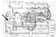
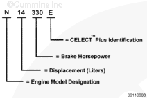
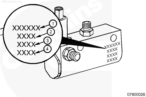
The engine dataplate provides the model identification and other important information about the engine.

Have the following engine data available when communicating with a Cummins Authorized Repair Location. The information on the dataplate is mandatory when sourcing service parts:

  1. Engine serial number (ESN)
  2. Control parts list (CPL)
  3. Model
  4. Advertised horsepower and rpm.
 
SMALL | MEDIUM | LARGE


For example, on CELECT™ Plus engines, the electronic control module
(ECM) dataplate is located on top of the ECM.

The abbreviations in the accompanying illustration are explained as follows:

p/n = part number
s/n = serial number
d/c = date code.
 
SMALL | MEDIUM | LARGE
   

Cummins Engine Nomenclature

TOC

The Cummins model name provides information as shown in the accompanying illustration.

 
SMALL | MEDIUM | LARGE
   

Component Dataplates

TOC

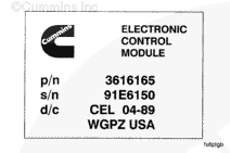
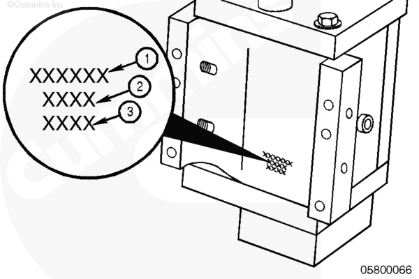
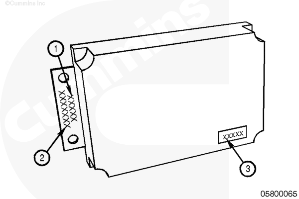
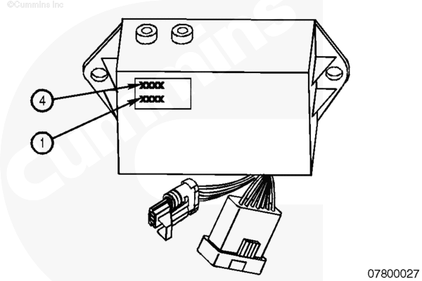
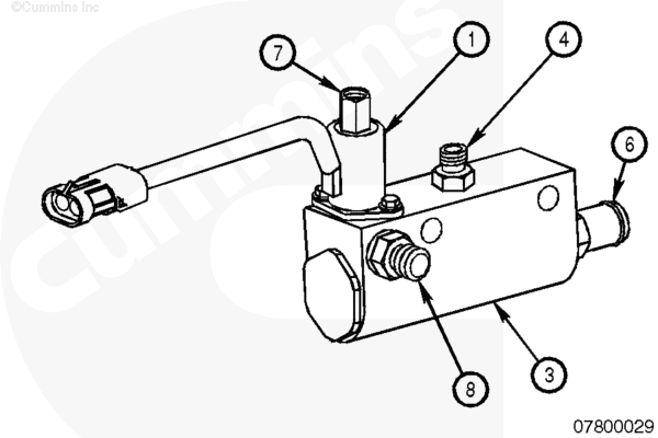
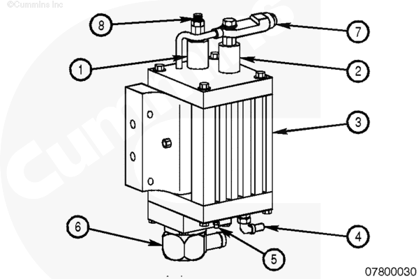
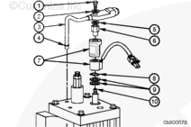
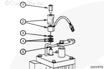
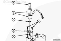
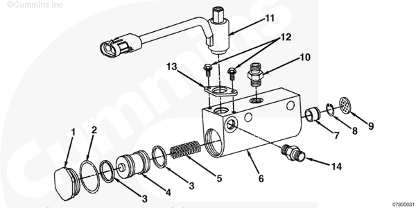
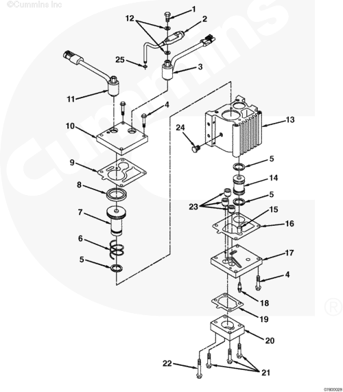
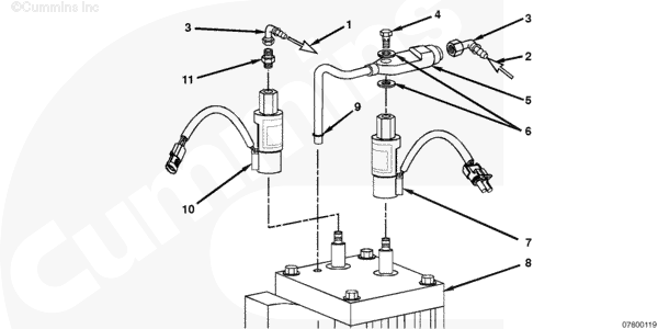
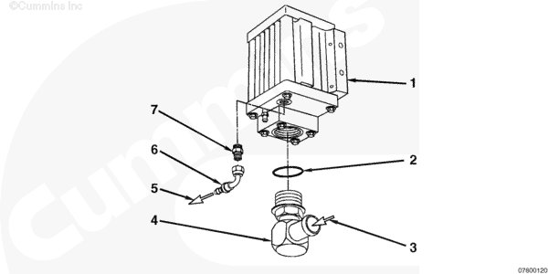
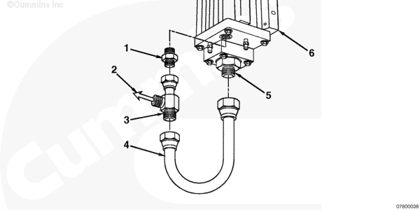
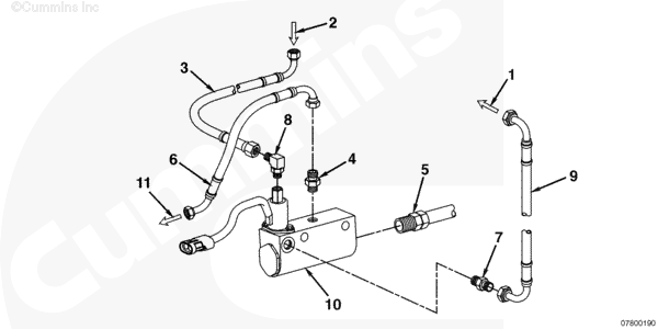
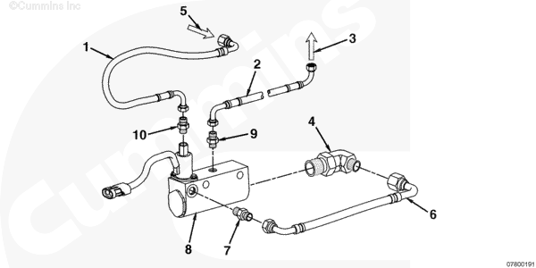
NOTE: There are two dataplates: One is stamped on the Centinel™ oil control valve and the other is stamped onto the Centinel™ control module. Please refer to the model listed on the dataplate when ordering repair/replacement parts.

SMALL | MEDIUM | LARGE
Dual-Piston
SMALL | MEDIUM | LARGE
Single-Piston

The part number of the Centinel™ oil control valve is stamped on the valve. The information contained on the oil control valve is:

  1. Cummins
  2. Part number and voltage
  3. Date code.

  1. Cummins
  2. Part number and voltage
  3. Supplier identification code
  4. Date code.

SMALL | MEDIUM | LARGE
High-Horsepower
SMALL | MEDIUM | LARGE
Heavy-Duty

The Centinel™ control module has a dataplate located on the front cover. The information contained on the dataplate is:

  1. Serial number
  2. Base module part number.

There are three different Centinel™ control module part numbers available for use on the Centinel™ system. They are:

  1. High-Horsepower 12 VDC or 24 VDC, module part number
  2. Heavy-Duty 12/24 VDC, module part number.

When ordering replacement parts, order by the part number that is specific to your system configuration.

Valve Configurations

TOC

SMALL | MEDIUM | LARGE
Single-Piston
SMALL | MEDIUM | LARGE
Dual-Piston

Centinel™ Oil Control Valve Components

  1. Burn solenoid
  2. Make-up solenoid
  3. Centinel™ oil control valve
  4. Oil to engine
  5. Air bleed valve
  6. Make-up oil supply inlet
  7. Engine oil to Centinel™ oil control valve
  8. Engine oil to fuel.

Exploded View

TOC

Make-Up Solenoid (dual-piston)

  1. Banjo screw
  2. Nylon washer
  3. Bypass oil tube
  4. Bypass oil tube o-ring
  5. Nylon washer
  6. Solenoid retaining nut
  7. Solenoid cover and solenoid coil
  8. Spring washer
  9. Two washers/spacers
  10. O-ring.
 
SMALL | MEDIUM | LARGE


Burn Solenoid (dual-piston)

  1. Solenoid retaining nut
  2. Solenoid cover and solenoid coil
  3. Spring washer
  4. Two washers/spacers
  5. O-ring.
 
SMALL | MEDIUM | LARGE


Solenoid (single-piston)

  1. Solenoid retaining nut
  2. Solenoid cover and solenoid coil
  3. Spring washer
  4. Screw
  5. Clamping plate
  6. O-ring.
 
SMALL | MEDIUM | LARGE

SMALL | MEDIUM | LARGE
Oil Control Valve (single-piston)

  1. Plug
  2. O-ring
  3. Seal, u-ring
  4. Piston
  5. Spring, compression
  6. Body, oil control valve
  7. Check valve
  8. Retaining ring
  9. Screen
  10. Check valve
  11. Valve, solenoid
  12. Screw
  13. Clamping plate
  14. Male union.

SMALL | MEDIUM | LARGE
Oil Control Valve (dual-piston)

  1. Screw, banjo
  2. Tube, lubricating oil bypass
  3. Valve, solenoid (make-up)
  4. Capscrew, hex flange head, M6 x 30 (7 places)
  5. Seal, u-ring (three places)
  6. Spring, compression
  7. Piston, oil control valve
  8. Seal, u-ring (one place)
  9. Gasket, control valve body
  10. Cover, oil control valve
  11. Valve, solenoid (burn)
  12. Washer, banjo screw
  13. Body, oil control valve
  14. Piston, oil control valve
  15. Valve, check
  16. Gasket, oil control valve
  17. Cover, oil control valve
  18. Fitting, bleed screw
  19. Gasket, connection
  20. Connection, oil supply
  21. Capscrew, hex flange head, M6 x 35 (3 places)
  22. Capscrew, hex flange head, M6 x 50
  23. Valve, check (three places)
  24. Fitting, vent
  25. O-ring.

SMALL | MEDIUM | LARGE
Centinel™ Dual-Piston Plumbing Assembly (burn-only and burn with make-up – top)

  1. Engine oil to fuel return line
  2. Engine oil to Centinel™ oil control valve
  3. Number 4 face sealing o-ring 90-degree elbow
  4. Banjo screw
  5. Lubricating oil bypass tube
  6. Washer
  7. Make-up solenoid
  8. Centinel™ oil control valve
  9. O-ring
  10. Burn solenoid
  11. 3/8-24 straight-thread o-ring adapter.

NOTE: The plumbing on the top of the oil control valve is the same for both the burn-only and burn with make-up systems.

SMALL | MEDIUM | LARGE
Centinel™ Dual-Piston Burn with Make-Up Plumbing Assembly (bottom)

  1. Centinel™ oil control valve
  2. O-ring
  3. Make-up oil to Centinel™ oil control valve
  4. Make-up oil supply inlet
  5. Make-up oil to engine
  6. Number 6 face sealing o-ring 90-degree elbow
  7. 9/16-18 straight-thread o-ring adapter.

NOTE: The plumbing on the top of the oil control valve is the same for both the burn-only and burn with make-up systems.

SMALL | MEDIUM | LARGE
Centinel™ Dual-Piston Burn-Only Plumbing Assembly (bottom)

  1. Male union
  2. To engine oil sump
  3. Male tee with female run
  4. Oil transfer tube
  5. Male union
  6. Dual-piston oil control valve.

NOTE: The plumbing on the top of the oil control valve is the same for both the burn-only and burn with make-up systems.

SMALL | MEDIUM | LARGE
Single-Piston Burn with Make-Up Plumbing and Mounting Assembly

  1. To fuel return
  2. Oil supply
  3. Oil supply hose
  4. Outlet check valve
  5. Oil from make-up tank
  6. Oil replenishment hose
  7. Male union connector
  8. Male union elbow
  9. Oil burn hose to fuel return
  10. Oil control valve
  11. Clean oil to engine.

NOTE: On ISM engines, 3 and 2 are reversed.

SMALL | MEDIUM | LARGE
Single-Piston Burn-Only Plumbing and Mounting Assembly (ISM engines)

  1. Oil supply hose
  2. Oil burn hose to fuel return
  3. To fuel return
  4. Oil transfer elbow
  5. Oil supply
  6. Oil transfer hose
  7. Male union
  8. Oil control valve
  9. Outlet check valve
  10. Male union.

Last Modified:  22-Apr-2004