Centinel System – Master Repair Manual – 209-001   System Description

General Information

TOC

The Centinel™ system is a continuous oil replacement system of electromechanical design. The Centinel™ system can be “integrated” (purchased from the factory) on selected engine models or “aftermarket” (retrofitted to existing engines). The Centinel™ system extends oil and oil filter change intervals through continuous oil exchange. This is accomplished by injecting oil at a controlled rate, proportional to fuel consumed, into the fuel system for consumption. Make-up oil is introduced into the engine at a rate equal to the oil consumed. This oil addition occurs in one of two ways. In one case there is an onboard fresh oil tank. Oil is delivered from this tank by the Centinel™ valve to the engine sump during each cycle of the valve. The Centinel™ system monitors the oil level in the make-up tank. In a second version of the system, make-up oil is added manually to the engine oil sump during the daily preventative maintenance process. This burn-only system is only for those operators who have routine, daily maintenance practices in place.

NOTE: The burn-only system differs from the standard Centinel™ system. The standard system utilizes a make-up oil tank to continuously replenish oil removed from the engine via the oil control valve and burned. In the burn-only system, there is no make-up oil tank; therefore, oil must be checked and replenished by the customer by adding oil directly to the engine. The Centinel™ burn-only system is designed for customers who check and maintain required engine oil levels on a daily basis.

NOTE: Vehicles domiciled in California can not use any system
(like Centinel™) that blends used engine oil with diesel fuel (check CARB regulations).

Theory of Operation

TOC

The oil control valves are electromechanical piston valves that exchange the used engine oil with fresh oil (if using a make-up tank). The valves use engine oil rifle pressure to drive piston displacement. In order for the control module to activate the system, the oil rifle pressure must exceed a predetermined value. The control module has been programmed to monitor the oil pressure and prevent operation until oil pressure rises enough to drive the valve. The control module will not permit the valve to operate until a predetermined time period has elapsed (high-horsepower), or until the engine reaches its operating temperature of 52°C [126° F] (heavy-duty CELECT™).

Dual-Piston Centinel™ Oil Control Valve Operation

Aftermarket systems use the dual-piston oil control valve to control the exchange of engine oil. The burn piston displaces 34 cc of engine oil into the fuel return line to be mixed with the fuel in the fuel tank. The make-up piston displaces 17 cc of fresh engine oil into the oil pan via the engine block (if using a make-up tank). The oil control valve can control the make-up piston independent of the burn piston. The make-up piston cycles twice for every burn piston cycle.

Single-Piston Centinel™ Oil Control Valve Operation

The systems that use the single-piston oil control valve use one piston to control the exchange of oil. One end of the piston displaces 17 cc of used engine oil to the fuel return line while the other end of the piston delivers 17 cc of fresh engine oil into the oil pan via the engine block (if using a make-up tank).

There are several distinct Centinel™ systems available:

For aftermarket systems using the dual-piston valve, there is one system for the high-horsepower K19/K38/50 PT® fuel system engines, and another for the heavy-duty L10/M11/N14 CELECT™ engines. These are available in both 12- and 24-VDC configurations.
For aftermarket systems using the single-piston valve, there is one system for the ISM engine in 12-VDC configuration.
For integrated systems, there is one system for the ISM engine in a 12-VDC configuration and one system for the QSK45/60 in 24-VDC configuration.

The following table summarizes the Centinel™ oil control valve and control module configurations.

Centinel™ Product Matrix
Engine Family Control Module Oil Control Valve
High-Horsepower Centinel™ Control Module Heavy-Duty Centinel™ Control Module ECM (1) Dual-Piston Single-Piston
L10/M11(2)   X   X  
ISM     X   X
N14(2)   X   X  
K19 X     X  
K38 X     X  
QSK45     X   X
K50 X     X  
QSK60     X   X

ECM = engine control module

CELECT™ and CELECT™ Plus electronic engines


NOTE: With the additional function of controlling the Centinel™ oil control valve by the ECM, a second fan clutch or Spicer Automate-2 transmission can not be used.

The following is a listing of components OEMs will be required to supply for the integrated Centinel™ system:

  • make-up oil tank
  • remote oil level switch for make-up tank
  • hose and fittings for plumbing from make-up tank to oil control valve mounted on the engine.

or, for burn-only

  • wiring harness “jumper” from remote oil level switch to engine OEM interface connector (31-pin connector for oil level switch).

Any of these systems can be configured to use the onboard make-up tank or as burn-only systems, depending on the particular installation.

The components of the Centinel™ system are shown in the “Kit Structures”
and “System Diagrams” at the end of this section.

The Centinel™ system is designed to maintain oil quality in an acceptable range. Oil analysis is required to monitor both the engine and Centinel™ system performance. The Guidelines for Oil Condemnation from the Cummins Engine Oil Recommendations, Bulletin 3810340, generally apply, but must be modified and expanded for the Centinel™ operation.

Refer to Procedure 018-017 for Centinel™ oil property guidelines. Used oil analysis can help monitor engine condition when viewed with the awareness of the Centinel™ system and the guidelines. Refer to Procedure 007-083.

Control Module Inputs

TOC

Low Oil Level Switch

The Centinel™ control module requires a digital open/close contact level sensor to determine whether or not the make-up tank has oil in it. If the Centinel™ control module reads closed contact from the sensor, the make-up tank is deemed to be full of oil. If the sensor contact is opened, the make-up tank is deemed to be low. Under these conditions, the red diagnostic light indicator will flash continuously, indicating the make-up tank is low. Once filled to the point that the sensor signal input is high, the red diagnostic lamp indicator will stop flashing.

This switch detects a low oil level condition in the Centinel™
make-up tank.

This switch has two positions, OIL DETECTED and OIL NOT DETECTED. When the switch is in the OIL DETECTED position, the Centinel™ system operates normally. When the switch is placed into the OIL NOT DETECTED position, a fault code activates, and the Centinel™ system stops metering engine oil. Metering resumes when the switch is returned to the OIL DETECTED position.

This switch can be any of several devices, an SPST magnetic or float-type switch is typically used. The switch is defined in the following table. When using a switch with physical contacts, gold-plated contacts are recommended to obtain reliable switching at low voltages and currents, but silver contacts are acceptable if the switch is hermetically sealed.

Refer to Procedure 018-017 for the remote oil level switch specifications.

SMALL | MEDIUM | LARGE
Cummins-Supplied Oil Level Switch

Low Oil Level Switch Mating Connector

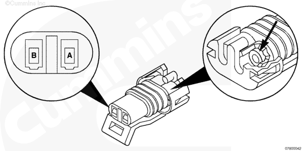
This connector mates to the acceptable low oil level switch for the Centinel™ system. This connector carries signals that permit detection of a low oil level condition in the Centinel™ make-up tank. This connector is required for Centinel™ integrated systems if the low oil level switch is installed.

This connector is a two-way Packard Metri-Pack 150 Series. The connector is black to distinguish it from similar connectors with different keying. Terminals are tin-plated pins. Cable seals are required. A secondary lock
(TPA) is required (refer to Low Oil Level Switch Mating Connector Parts List table).

SMALL | MEDIUM | LARGE
Low Oil Level Switch Mating Connector

K19, K38, and K50 Engines

The high-horsepower Centinel™ control module will be mounted to the Centinel™ valve mounting bracket. The Centinel™ control module must be programmed via INSITE™ with the correct parameters for your application. The Centinel™ control module monitors system operation.

L10, M11, and N14 Engines

The heavy-duty Centinel™ control module will be mounted on the make-up oil tank or other visible location. The Centinel™ control module will have one external interface connector, and one calibration/service connector. The external interface connector is a 12-pin sealed Deutsch interlock-type connector. The calibration/service connector is a 3-pin Packard sealed connector and will mate with the matching calibration connector. The Centinel™
control module is pre-programmed and not programmed via INSITE™.

ISM, QSK45, and QSK60 Engines

The integrated system used on ISM, QSK45, and QSK60 engines utilizes the existing engine ECM. Upon installation of the Centinel™ system, a new ECM code will need to be downloaded to activate the Centinel™
valve.

Control Module Outputs

TOC

K19, K38, and K50 Engines

The Centinel™ control module monitors system operation. If any parameters are not met, the system will shut down. During shutdown, the Centinel™ control module will continue to monitor fuel used and count the number of oil replenishment cycles that it missed. Once the system is put back into service, the Centinel™ control module will make up
the missed cycles to maintain oil quality or log a fault, indicating an oil change is required. Any Centinel™ faults will light the diagnostics lamp mounted on the tank or elsewhere.

L10, M11, and N14 Engines

If any parameters are not met, the system will shut down. During shutdown, the Centinel™ control module will continue to monitor fuel used and count the number of oil replenishment cycles that it missed. Once the system is put back into service, the Centinel™ control module will make up the missed cycles to maintain oil quality or log a fault indicating an oil change is required. Any Centinel™ faults will light the diagnostics lamp mounted on the tank or elsewhere.

ISM, QSK45, and QSK60 Engines

By using the engine’s ECM, any Centinel™ faults will light the maintenance (Fluids) and/or warning lamps on the dash or elsewhere (INSITE™
will also be able to read these faults and RoadRelay™ will display them).

Diagnostic Fault Codes

TOC

Integrated Systems

The integrated Centinel™ system is mounted on the engine and is electronically controlled by the electronic control module (ECM). The ECM controls the timing and number of oil control valve strokes based on the engine’s duty cycle. By using the engine’s ECM, any Centinel™ faults will light the maintenance (Fluids) and/or warning lamps on the dash or elsewhere. (INSITE™
will also be able to read faults and RoadRelay™ will display them.)

Once fault is identified:

  1. Refer to Section TF.
  2. Clear the fault code. Refer to the appropriate fuel system troubleshooting and repair manual.

Aftermarket Dual-Piston Systems

The diagnostic lamp display is attached to the Centinel™ system make-up oil tank on High-Horsepower engines. The lamp is a component of the Centinel™ control module assembly and attached to the make-up oil tank on Heavy-Duty engines.

For burn-only systems, there are two warning lamps. They are green and red in color. The green lamp indicates that the Centinel™ system has power and is operating. The red lamp indicates that a system parameter is not within specification. The lamps must be mounted in a location where they can be easily seen.

If the red lamp is illuminated, turn the keyswitch to the OFF position and back to the ON position. Immediately look at the red lamp. It should start flashing a three-digit code. This code will be associated with a fault code. The codes are read as follows:

  1. If the red lamp flashes three times, the first digit is “3”;
    the number of flashes will indicate the first digit of the code.
  2. There will be a pause.
  3. If the red lamp flashes four times, the second digit of the fault code will be “4”; the number of flashes will indicate the second digit of the code.
  4. There will be another pause.
  5. If the red lamp flashes two times, the third digit of the code is “2”;
    the number of flashes will indicate the third digit of the code.
  6. In this example, the code is 3-4-2. Fault Code 342 is a Centinel™
    Control Module Calibration fault.

At this point, there will be a longer pause before the fault code will be flashed again. This process will occur four times. After the fourth time, the fault lamp will stay red if the fault is still active. To read the code again, turn the key switch to the OFF position and back to the ON position. The code will flash again.

Once the correct fault code is identified, refer to Section TF of this manual and begin troubleshooting.

Clearing Active Faults

    Heavy-Duty Engines

  • Turn the keyswitch ON.
  • Make certain the engine is not running.
  • Remove the calibration plug
  • Install the service plug.

NOTE: Wait 2 minutes to install the service plug if installing immediately after the engine is shut down.

  • Remove the service plug.
  • Verify that all the faults are cleared.

NOTE: The service plug is a red, two-wired plug.

    High-Horsepower Engines

  • Turn the keyswitch ON.
  • Make certain the engine is not running.
  • Install the service plug.

NOTE: Wait 2 minutes to install the service plug if installing immediately after the engine is shut down.

  • Remove the service plug.
  • Verify that all the faults are cleared.

NOTE: The service plug is a red, two-wired plug.

Service Mode

When Centinel™ is placed into the service mode, the oil control valve is continuously cycling independent of fuel consumption data.

The following is a general procedure for putting the Centinel™
module into the service mode:

    Heavy-Duty Engines

  • Turn the keyswitch OFF.
  • Calibration plug installed.
  • Turn the keyswitch ON.
  • Start the engine.
  • Remove the calibration plug and install the service plug. Look for the green LED to flash.

NOTE: If the engine is left running while attempting to exit the service mode, it can take up to 4 minutes to exit the service mode.

To exit the service mode, remove the service plug and install the required calibration plug.

    High-Horsepower Engines

  • Turn the keyswitch OFF.
  • Service plug not installed.
  • Turn the keyswitch ON.
  • Start the engine.
  • Install the service plug.

NOTE: If the engine is left running while attempting to exit the service mode, it can take up to 4 minutes to exit the service mode.

To exit the service mode, remove the service plug.

Installation Recommendations

TOC

 CAUTION 

The plumbing and make-up tank included in the Centinel™ kits may not be adequate for use in all applications. All applicable local, state and federal regulations and any insititutional codes must be consulted to ensure that all components satisfy these regulations and codes. Any component that does not satisfy any applicable regulation or code must be replaced with a component that does.

The oil control valve is designed to perform at -9°C [16°F]
with a 15W-40 engine oil. It is important to understand that the oil control valve can not operate as intended if the oil viscosity exceeds this limit.

  • The Cummins supplied make-up oil tank comes in two sizes, 4-gallon and 6.5-gallon usable capacity.
  • The make-up tank fill cap location must be easily accessible.
  • The make-up tank must be located so that visual checks can be easily done.

If a customer wishes to procure or fabricate a make-up tank, it must contain a low oil level sensor. The specific requirements for this sensor are detailed later in this section. Additionally, the make-up oil tank must contain a filtered vent to the atmosphere.

Dual-Piston Mounting Location

NOTE: For cabover designs, the make-up tank can not be mounted on the cab/sleeper due to tilting of cab for engine servicing.

  • Full level of the make-up tank can be no higher than 8.2 meters
    [27 feet] above the make-up inlet connection of the Centinel™ oil control valve.
  • Bottom of the make-up tank can be no lower than the make-up inlet connection on the oil control valve.
  • Typical mounting locations for the make-up oil tank on heavy-duty trucks could be:
    • Part of fuel tank (preferred location – fuel will warm make-up tank)
    • The exhaust muffler stanchion
    • The back wall of the cab/sleeper
    • The frame rail directly behind the cab.
  • Typical mounting locations for the make-up oil tank on high-horsepower applications could be:
    • The decking above the engine compartment
    • The frame rail of the vehicle in a visible location.

Single-Piston Mounting Location

NOTE: For cabover designs, the make-up tank can not be mounted on the cab/sleeper due to tilting of cab for engine servicing.

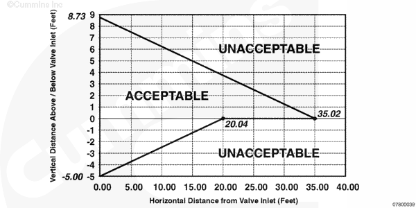
  • Full level of the make-up tank can be no higher than 2.6 meters
    [8.5 feet] above the make-up inlet connection of the integrated Centinel™
    oil control valve. Vehicle angularity capability must be taken into consideration when locating the tank.
  • Bottom of the make-up tank can be no lower than 0.9 meters [3.0 feet] below the make-up inlet connection on the integrated Centinel™
    oil control valve. Vehicle angularity capability must be taken into consideration when locating the tank. (Refer to Table 1.)
  • Distance from make-up oil tank to integrated Centinel™ valve must be as short as possible. See Table 2 for guidelines.
  • Typical mounting locations for the make-up oil tank on heavy-duty trucks could be:
    • Part of fuel tank (preferred location – fuel will warm make-up tank)
    • The exhaust muffler stanchion
    • The back wall of the cab/sleeper
    • The frame rail directly behind the cab.

SMALL | MEDIUM | LARGE
Table 1, Tank Installation Relative to Valve Inlet for Single-Piston System (tank must be located within the outlined area)

Design Requirements (dual- and single-piston)

NOTE: A warning must be added to inspect tank internally if damage has occurred.

  • The preferred make-up tank design is as a segmented part of the fuel tank (see mounting height restrictions above). This offers many advantages:
    • Warms the fresh lubricating oil for better cold flow
    • Is in a protected location
    • Eliminates the need for separate tank and its mounting support with mounting hardware.
  • The tank must have an internal standpipe (or drop tube, depending on tank location and design). This standpipe or drop tube must be designed to prevent debris (sediment, dirt, etc.) from entering into the make-up line. The standpipe or drop tube must have at least 1/2-inch clearance from bottom of the make-up tank.
  • The tank can have a drain in the bottom of the tank to allow for removal of sediment, dirt, etc. that will collect at the bottom of the make-up tank. It is recommended that this tank be drained every 4000 hours/500,000 miles to remove these contaminants.
  • Minimum ID for line from make-up tank to the oil control valve is 3/4 inch. All fittings must be sized for use with this 3/4 ID minimum requirement. The larger the ID, the better for cold flow of oil.
  • A boss for a remote oil level switch is required in the make-up tank. This switch must be located so that when the tank has a minimum of 1/2 gallon of usable oil remaining, the sensor will activate. This sensor must be above the 1/2-inch clearance value given earlier for the standpipe/drop tube in the make-up tank. Thread size for boss is dependent on remote oil level switch used.
  • The tank must be vented. This vent must
    be designed and located against debris entering through this vent or the vent becoming plugged with debris (dirt, mud, snow, etc.).
  • The tank must be designed with an expansion space for the oil as it is warmed. This expansion space must be a minimum of 3 percent of the volume of the tank.
  • The tank sizing must be based on the fuel usage and desired miles before refilling the make-up tank. Remember that the capacity is the usable gallons in the tank, not overall capacity, and that oil usage is dependent on the fuel usage of the vehicle.
  • The tank must be designed to withstand at least 124 kPa [18 psi]. When priming the make-up system, a maximum of 124 kPa [18 psi]
    is to be used. The tank can be equipped with a connection for pressurization.
  • The make-up tank must be designed so that a visual check or gauge check of the oil level in the tank can be easily done. If a gauge system is used, then it must be easily visible to the driver and/or maintenance person.
  • The plastic make-up tanks designed for use with the aftermarket Centinel™ system can be used with the integrated Centinel™ system. These Cummins aftermarket make-up tanks come in 15.1 liter [4-gallon] and 24.6 liter [6.5-gallon] usable oil sizes.
  • The fill neck section of the make-up tank can have a screen in the filler tube to catch any debris that can enter the tank (such as dirt, etc. that adheres to cap). Screen size must be 100 x 100 mesh. This screen must be easy to clean. There must not be a filter installed either in the line between the make-up tank/valve or a filter at the outlet of the tank; these would cause restrictions for cold oil flow.

Make-Up Hose

The make-up hose must have a minimum 3/4-inch inner diameter. A single-braided reinforced weather-resistant hose with an inner tube of oil-resistant Nitrile or Neoprene synthetic rubber is recommended. Hose conforming to SAE 100R6 in accordance with SAE J517 will meet this specification. This hose must be designed for use with lubricating oil within a temperature range of -40 to +150°C [-40 to +302°F]. It also must
work in air temperatures up to 70°C [158°F].

The hose must not leak, burst or indicate any sign of failure when subjected to a maximum working pressure of 300 psi or a vacuum of 15 in Hg.

All fittings that have o-rings must have o-rings made of viton.

Last Modified:  22-Apr-2004