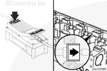
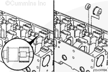
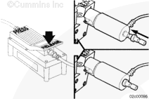
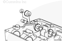
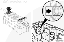
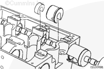
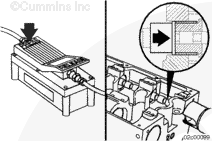
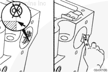
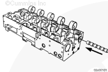
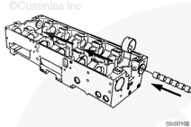
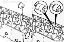
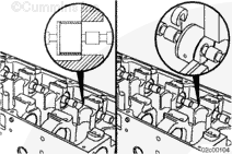
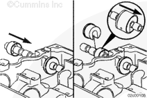
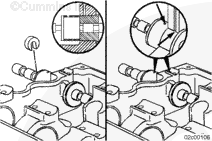
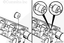
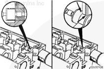
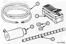
Make sure to select the proper-size centering guides. This kit contains different-size centering guides for journals both with and without bushings installed. Selection of incorrect centering guides can result in damage to the journal and/or guides.
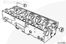
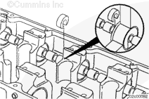
Install the centering guides in two of the camshaft bore ends.
NOTE: The centering guide can be installed in any of the holes, but keeping the wider distance is preferred.
Position the receiver spacer on the puller shaft with the open end facing the cylinder head.
NOTE: A receiver spacer has not been included in the valve camshaft bushing replacer kit, Part Number 3164088. Use receiver spacer, Part Number 3824864, or an appropriate-size spacer from another kit.
Make sure to install the proper-size bushing driver. Selection of incorrect bushing driver can result in damage to the camshaft bushing, journal cylinder head bore, and tool equipment.
Position the bushing driver on the puller shaft next to the bushing that is being removed.
Slide the bushing driver into the camshaft bushing until it stops against the flange of the bushing driver.
Keep hands clear of the journal area when operating the pedal of the air/hydraulic pump. Serious injury can result if hands are caught between journal and bushing area when operating the air/hydraulic pump pedal.
Push down on the PRESS side of the air/hydraulic pump pedal and hold until the cam bushing is out of the bore.
Keep hands clear of the journal area when operating the pedal of the air/hydraulic pump. Serious injury can result if hands are caught between journal and bushing area when operating the air/hydraulic pump pedal.
Push down on the PRESS side of the air/hydraulic pump pedal and hold until the rear camshaft bushing and centering guide are out of the bore.
Keep hands clear of the journal area when operating the pedal of the air/hydraulic pump. Serious injury can result if hands are caught between journal and bushing area when operating the air/hydraulic pump pedal.
Push down on the PRESS side of the air/hydraulic pump pedal and hold until the camshaft bushing and centering guide are out of the bore.
Make sure to select the proper-size centering guides. This kit contains different-size centering guides for journals both with and without bushings installed. Selection of incorrect centering guides can result in damage to the journal and/or guides.
Install the centering guides into both camshaft bore ends.
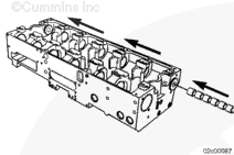
Slide the puller shaft through the centering guide and into the number 2 journal. Place a camshaft bushing, if desired, over the end of the puller shaft.
Move the puller shaft through the number 3 journal and do the same as above.
Continue through each inner journal until the puller shaft is completely through the opposite-end centering guide.
Make sure to install the proper-size bushing driver. Selection of incorrect bushing driver can result in damage to the camshaft bushing, journal, and tool equipment.
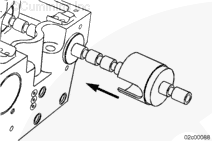
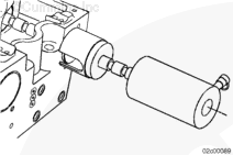
Position the proper bushing driver on the puller shaft next to the bushing being installed.
Slide the camshaft bushing over the bushing driver.
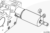
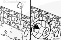
It is very important that the oil ports on the camshaft bushings being installed be aligned with the oil ports in the journal. Misalignment of cam bushing oil port to journal oil port can result in damage to the engine.
Push the bushing driver over until the cam bushing just touches the cylinder head.
Install the stop collar into the groove on the puller shaft closest to the end of the bushing driver.
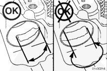
Rotate the camshaft bushing until the oil port is aligned with the oil port of the bore.
Keep hands clear of the journal area when operating the pedal of the air/hydraulic pump. Serious injury can result if hands are caught between journal and bushing area when operating the air/hydraulic pump pedal.
Push down on the PRESS side of the air/hydraulic pump pedal to pull the cam bushing into the cylinder head. As the camshaft bushing oil port comes close to the bore oil port, let up on the pedal.
Lightly tapping the PRESS side of the air/hydraulic pump pedal will provide control to stop the camshaft bushing in the desired position.
Make sure to install the proper-size bushing driver. Selection of incorrect bushing driver can result in damage to the cam bushing, journal, and tool equipment.
Place the camshaft bushing over the end of the puller shaft.
Position the bushing driver on the puller shaft and slide the camshaft bushing onto the bushing driver.
It is very important that the oil ports on the camshaft bushings being installed be aligned with the oil ports in the journal. Misalignment of camshaft bushing oil port to journal oil port can result in damage to the engine.
Push the bushing driver over until the camshaft bushing just touches the cylinder head.
Install the stop collar into the groove on the puller shaft closest to the end of the bushing driver.
Rotate the camshaft bushing until the oil port is aligned with the oil port of the bore.
Keep hands clear of the journal area when operating the pedal of the air/hydraulic pump. Serious injury can result if hands are caught between journal and bushing area when operating the air/hydraulic pump pedal.
For front and rear bushing installation, move the centering guides to journals 2 and 6.
Push down on the PRESS side of the air/hydraulic pump pedal to pull the camshaft bushing into the cylinder head. As the camshaft bushing oil port comes close to the bore oil port, let up on the pedal.
Lightly tapping the PRESS side of the air/hydraulic pump pedal will provide control to stop the camshaft bushing in the desired position.
Make sure to install the proper-size bushing driver. Selection of incorrect bushing driver can result in damage to the camshaft bushing, journal, and tool equipment.
Position the proper bushing driver on the puller shaft.
Slide the camshaft bushing over the bushing driver.
It is very important that the oil ports on the camshaft bushings being installed be aligned with the oil ports in the journal. Misalignment of camshaft bushing oil port to journal oil port can result in damage to the engine.
Push the bushing driver over until the camshaft bushing just touches the cylinder head.
Install the stop collar into the groove on the puller shaft closest to the end of the bushing driver.
Rotate the camshaft bushing until the oil port is aligned with the oil port of the bore.
Keep hands clear of the journal area when operating the pedal of the air/hydraulic pump. Serious injury can result if hands are caught between journal and bushing area when operating the air/hydraulic pump pedal.
NOTE: The centering guide will be forced into the receiver spacer when the bushing and driver are pulled into the bore.
Push down on the PRESS side of the air/hydraulic pump pedal to pull the camshaft bushing into the cylinder head. As the camshaft bushing oil port comes close to the bore oil port, let up on the pedal.
Lightly tapping the PRESS side of the air/hydraulic pump pedal will provide control to stop the camshaft bushing in the desired position.
Hello, I'm Jack, a diesel engine fan and a blogger. I write about how to fix and improve diesel engines, from cars to trucks to generators. I also review the newest models and innovations in the diesel market. If you are interested in learning more about diesel engines, check out my blog and leave your feedback.
View all posts by Jack



 CAUTION

 WARNING