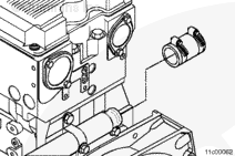
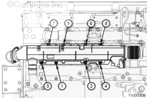
Keep all protective caps on the EGR cooler in place while grinding clearance in the upper mounting bracket. Failure to do so could cause progressive damage to the engine once the EGR cooler is installed. It’s important to prevent any debris from entering the cooler.
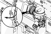
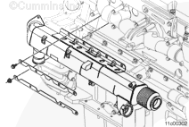
Inspect for an interference fit between the upper EGR cooler mounting bracket and the lower portion of the exhaust manifold flange. If this interference is present, grind a clearance on the upper EGR cooler mounting bracket in the area shown in the illustration.
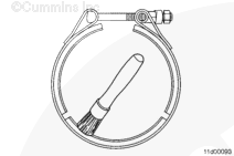
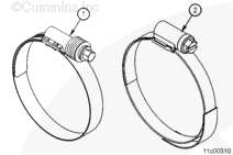
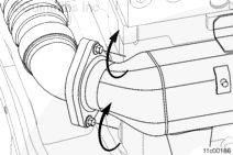
Do not use air tools to remove or install the nut on the v-band clamp. Use of these tools can seriously damage the threads or the bolt and cause the clamp to not be able to be reused.
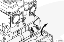
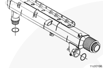
Position the v-band clamp onto the EGR cooler inlet connection.
Hello, I'm Jack, a diesel engine fan and a blogger. I write about how to fix and improve diesel engines, from cars to trucks to generators. I also review the newest models and innovations in the diesel market. If you are interested in learning more about diesel engines, check out my blog and leave your feedback.
View all posts by Jack


 CAUTION
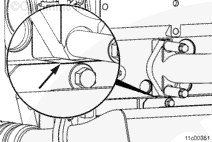
;)
;)
;)
;)
;)
;)
;)
;)
;)
;)
;)
;)
;)
;)
;)
;)
;)
;)
;)
;)
;)
;)
;)
;)