General Information |
|||||||||||||
|
All Delco Remy America alternators are rated for inlet air temperatures of -35 to 93°C [-31 to 200°F], measured 25.4 mm [1 in] from the rear of the unit, except for the 26SI. The 26SI has a maximum rating of 85°C [185°F] because of the sealed electronics. Avoid mounting the alternator near any heat sources, such as manifolds, turbochargers, and so forth. Adequate clearance must also be provided at the rear of the alternator for cooling air to enter (the alternator fan pulls air through toward the front of the unit). The second most common cause of failure of Cummins® alternators is contamination by dirt, chemicals, water, or unknown substances. While the alternator is laboratory tested to withstand salt spray, dust, and high humidity, it is necessary to mount the alternator to minimize environmental and application contamination. Exposure to salt spray over an extended period of time will shorten the alternator life, as well as increase circuit resistance by causing corrosion to terminal connections for all electrical components. Exposure to engine oil or oil mist from the engine breather tubes can cause brush problems in brush alternators, as well as attract other debris. Any contamination of the rear of the alternator can reduce airflow, which will eventually overheat the diodes. If operating in extreme environments, especially off-road, the 21SI can be installed with a dust shield, which has shown to reduce the effects of extreme environments and improve alternator life. Debris shields have been developed for the 19SI, 22SI, and 23SI alternators. New debris shields have provisions for mounting an air duct in order to route clean air where necessary. Establish proper cable routing, and determine cable lengths. Avoid routing taut cables between connections. The maximum voltage drop in the charging system at rated alternator output is 0.5 VDC for a 12 VDC system, 1.0 VDC for a 24 VDC system, and 1.5 VDC for a 32 VDC system. The voltage drop in the charging system must be kept to a minimum in order to make sure enough voltage exists to charge the batteries. While all Delco Remy America alternators are negative grounds, it is suggested that a full copper return be provided to the negative (-) terminal of the batteries. This will also make sure that as the vehicle ages, corrosion of the frame and ground strap do not cause excessive voltage drops. Also, painted mounting brackets can prevent a complete electrical circuit. Be sure all electrical connections, including ground connections, are metal-to-metal connections.
Mounting HardwareThe operating range of the cranking motor and solenoid is -25 to 121°C [-13 to 250°F]. Military application starters have an operating range from -54 to 121°C [-65 to 250°F]. Locating the motor close to the exhaust manifold or other heat source can result in reduced motor performance with deterioration of insulation and rubber components. A minimum 50.8 mm [2 in] clearance is recommended. Where relocation or rotation is not possible, metal shielding can effectively be used to protect the starter from engagement in hot conditions. Establish proper cable routing. Avoid routing a taut cable between connections. When routing battery cables from the frame rails to the cranking motor, anchor the cables to the engine, transmission, or cranking motor, and allow for relative movement between the engine and the frame. It is highly recommended that a copper ground return be used and the frame not be relied upon for ground return in the starting circuit, which will prevent corrosion from creating excessive voltage drops. Using a copper ground cable is especially critical in applications using a wet flywheel housing, where reliance on frame grounding can create a current path through the crankshaft and main bearings. Limit the number of cables attached to the battery terminal of the solenoid to not more than two. When positioning the motor at the mounting location, it is desirable to place the solenoid above the centerline of the motor (preferably a minimum of 15 degrees above the horizontal). This will prevent potential accumulation of foreign material or moisture that can restrict operation in the tower portion of the shift lever housing. It also reduces the possibility of road debris being thrown up and breaking the solenoid cap.
Mounting Specifications
If the engine does not start within five seconds of cranking, follow the Cold Weather Starting Using Starting Fluid – With Mechanical or Electrical Metering Equipment (Ether) in Section 1 of the Operation and Maintenance Manual Signature and ISX Engines, Bulletin 3666311, or Procedure 101-004 (Cold Weather Starting) in Section 1 of the Operation and Maintenance Manual Signature and ISX Engines, Bulletin 3666251, or Operation and Maintenance Manual Industrial and Power Generation QSX15 Engines, Bulletin 3666243. Operating the cranking motor for more than 30 seconds at a time causes stress and/or severe internal heat buildup. A minimum two minute cooling period is necessary between extended cranking cycles. When mounting a magnetic switch on a vehicle, the axis of the plunger must be horizontal to the ground and perpendicular to the axis of travel of the vehicle. This is to make sure the switch is not activated by the movement of the vehicle. Do not mount the switch on the engine or any metal that can possibly resonate as a result of road or engine vibration. For engines with separate fuel shutoff solenoids, Cummins Inc. requires the use of two magnetic switches: one for the fuel shutoff circuit and one for the starting circuit. The fuel shutoff solenoid must not be wired to the “S” terminal of the starting motor. Wiring to the “S” terminal will cause the shutoff solenoid to fail.
|
|||||||||||||
 CAUTION
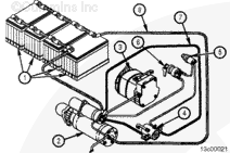


;)
;)
;)
;)