The fault code warning lamps let the operator know when a part or a system fault is detected. The yellow lamp may have the word WARNING printed on it. The red lamp may have the word STOP printed on it.
The fault code warning lamp’s circuit is a positive (+) 12-VDC (24-VDC in the United Kingdom or Europe) supply from the vehicle keyswitch, a yellow warning lamp (wire 16), and the red stop lamp (wire 6).
not present, there is a problem with the keyswitch line or the lamp has failed. Refer to the OEM troubleshooting and repair manual for repair procedures.
NOTE: The battery voltage will vary between vehicles, depending on the age and the condition of the batteries. There
must be enough voltage available to illuminate the lamp.
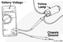
Touch the positive (+) multimeter probe to the red fault lamp terminal.
Touch the negative (-) multimeter probe to chassis ground.
Measure the voltage.
Repeat this check for the other terminal of the red fault lamp. The multimeter
must show battery voltage. If battery voltage is
not present, there is a problem with the keyswitch line or the lamp has failed. Refer to the OEM troubleshooting and repair manual for repair procedures.
Connect all components after the repair is complete.
Hello, I'm Jack, a diesel engine fan and a blogger. I write about how to fix and improve diesel engines, from cars to trucks to generators. I also review the newest models and innovations in the diesel market. If you are interested in learning more about diesel engines, check out my blog and leave your feedback.
View all posts by Jack


;)
;)
;)
;)
;)
;)