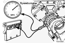
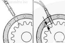
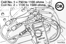
The shaft speed sensor senses the speed of the shaft by counting gear teeth. The ECM then calculates the shaft speed based on the number of teeth per revolution. The auxiliary governor can control the engine fueling to maintain a constant shaft speed.
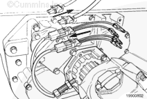
The shaft speed sensor has two coils. One coil is connected to the ECM and the other coil may be connected to some other vehicle device.
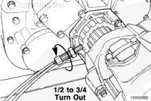
NOTE: Sensor design varies with the application. Refer to the equipment manufacturer’s manual to understand which type of shaft speed sensor is being used in a given location.
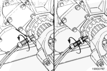
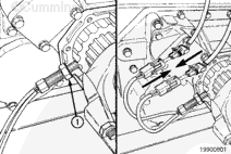
Install both of the connectors together until connectors “snap” into position. The connectors can be interchanged with each other without changing the performance of the system.
Lift the tab on the connectors and pull them apart.
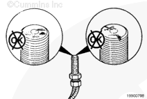
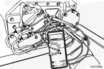
NOTE: When measuring the resistance value of the shaft speed sensor coils, use two female test leads, Part No. 3822996. This will allow the electrical leads of the sensor to be softly flexed to check for damaged or partially broken wire strands under the insulation.
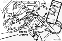
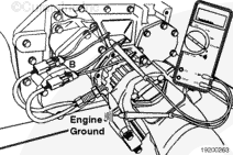
Measure the resistance between pin B of one of the connectors and the engine block. The multimeter
must show an open circuit (100k ohms or more).
NOTE: The open circuit specification (100k ohms or more) for the shaft speed sensor is higher than the open circuit specification used throughout the manual due to the sensitivity of the shaft speed sensor signal.
Hello, I'm Jack, a diesel engine fan and a blogger. I write about how to fix and improve diesel engines, from cars to trucks to generators. I also review the newest models and innovations in the diesel market. If you are interested in learning more about diesel engines, check out my blog and leave your feedback.
View all posts by Jack


 CAUTION


;)
;)
;)
;)
;)
;)
;)
;)
;)
;)
;)
;)
;)
;)
;)
;)
;)
;)
;)
;)
;)
;)