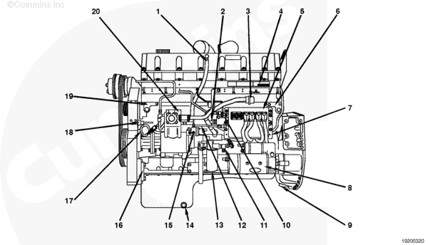
Engine Views
|
TOC |
|
- Blowby tube
- Ambient air pressure sensor
- 31-pin OEM connector
- Engine data tag
- Electronic control module (ECM)
- Engine serial number
- Cooling plate
- Starter
- Flywheel ring gear sensor
- Fuel outlet from cooling plate to injector rail
- Fuel vacuum
- Fuel outlet from pump
- Fuel filter with integral water-in-fuel sensor
- Oil drain plug
- Fuel rail pressure sensor
- Power steering pump mounting location
- Oil pressure/temperature sensor
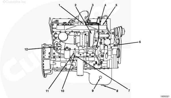
- Engine position sensor
- Freon compressor mounting location
- Air compressor.
- Either hookup
- Turbocharger
- Intake manifold temperature sensor
- Intake manifold pressure sensor
- Intake manifold
- Coolant temperature sensor
- Engine brake oil supply
- Oil pan drain plug
- Oil pan sump heater
- Oil pressure after filter
- Oil pressure before filter
- Coolant heater.
|
Last Modified: 07-Jul-2003
Published by Jack
Hello, I'm Jack, a diesel engine fan and a blogger. I write about how to fix and improve diesel engines, from cars to trucks to generators. I also review the newest models and innovations in the diesel market. If you are interested in learning more about diesel engines, check out my blog and leave your feedback.
View all posts by Jack
;)
;)
;)
;)