The silicone fluid in the vibration damper will become solid after extended service, which makes the vibration damper inoperative. An inoperative vibration damper can cause major engine or driveline failures.
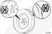
Check the vibration damper for evidence of fluid loss, dents, and wobble. Inspect the vibration damper thickness for any deformation or raising of the damper front cover plate.
When using a steam cleaner, wear safety glasses or a face shield as well as protective clothing. Hot steam can cause serious personal injury.
WARNING
When using solvents, acids, or alkaline materials for cleaning, follow the manufacturer’s recommendations for use. Wear goggles and protective clothing to reduce the possibility of personal injury.
WARNING
Wear appropriate eye and face protection when using compressed air. Flying debris and dirt can cause personal injury.
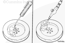
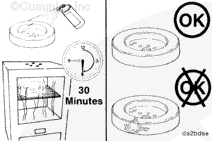
Use steam or solvent to clean the vibration damper.
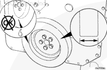
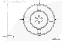
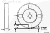
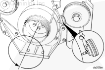
Measure and record the vibration damper thickness at two points at each of the four locations.
Measure the thickness at 3.18 mm [0.125 in] from the outer lip.
Measure the thickness at 25.4 mm [1.0 in] from the outer lip.
This procedure will result in a total of eight measurements.
If the variations between any of the eight measurements exceed 0.25 mm [0.010 in], or if the thickness at any point exceeds 45 mm [1.772 in], replace the vibration damper.
Clean the outside surface of the vibration damper.
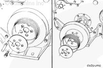
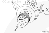
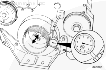
To measure damper eccentricity (out of round), install the dial indicator gauge, Part Number 3376050, and extension Part Number ST-537-4, on the gear cover as indicated.
Rotate the crankshaft with the accessory driveshaft one complete revolution (360 degrees), and record the total indicator movement.
Replace the vibration damper if the eccentricity exceeds 0.28 mm [0.011 in].
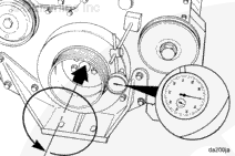
Rotate the crankshaft with the accessory driveshaft one complete revolution (360 degrees) while maintaining the position of the crankshaft either toward the front or the rear of the engine.
Record the total indicator movement.
Replace the damper if wobble exceeds 0.28 mm [0.011 in].
Hello, I'm Jack, a diesel engine fan and a blogger. I write about how to fix and improve diesel engines, from cars to trucks to generators. I also review the newest models and innovations in the diesel market. If you are interested in learning more about diesel engines, check out my blog and leave your feedback.
View all posts by Jack
 CAUTION


 WARNING


;)
;)
;)
;)
;)
;)
;)
;)
;)
;)
;)
;)
;)
;)
;)
;)
;)
;)
;)
;)
;)
;)
;)
;)