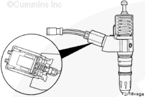
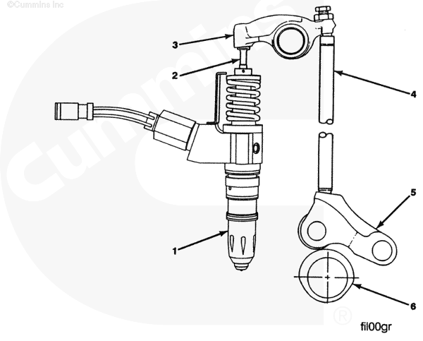
The 2002 ISM engine utilizes a different injector than the previous ISM engine, with flow characteristic changes and improved reliability. The injector is specially designed to maximize the benefit of cooled EGR and lower the emission levels.
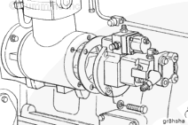
The fuel pump is located in the same location as a CELECT™ Plus fuel pump.
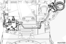
On CM876 engines, fuel flows from the fuel rifle at the rear of the engine to the aftertreatment shutoff valve. It then flows to the aftertreatment fuel injector.
When fuel is not flowing to the injector, fuel remaining between the aftertreatment shutoff valve number 1 and aftertreatment fuel injector passes through the aftertreatment shutoff valve number 2 and goes to drain.
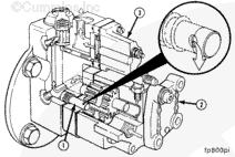
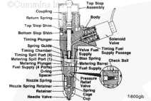
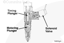
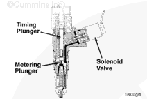
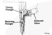
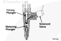
The injector assembly includes a solenoid valve, which controls the end of the fuel metering and the beginning of injection. The solenoid valve is normally open. An electronic signal from the ECM closes the valve as required.
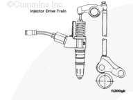
As the camshaft rotates, the timing plunger return spring forces the timing plunger upward.
Fuel flows past the metering check ball and into the metering chamber. This flow continues as long as the timing plunger is moving upward, and the injector control valve is closed.
Supply pressure, acting on the bottom of the metering piston, forces it to maintain contact with the timing plunger.
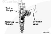
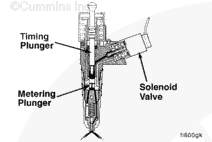
Fuel at supply pressure then flows into the timing chamber, thereby stopping metering piston travel.
During this time, the bias spring makes sure the metering plunger remains stationary; that it does not drift upward as the timing plunger moves upward. This same force against the metering plunger results in enough fuel pressure below the piston to keep the metering check ball seated.
A precisely metered quantity of fuel is now trapped in the metering chamber. This determines the quantity of fuel that will be injected.
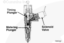
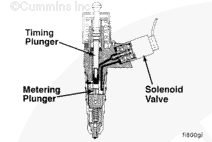
The timing plunger begins its downward travel. Initially, the injector control valve remains open, allowing fuel to flow from the timing chamber, through the injector control valve, and into the fuel supply passage.
At the appropriate time, as determined by the ECM, the injector control valve closes, trapping fuel in the timing chamber. This trapped fuel creates a solid hydraulic link between the timing plunger and the metering plunger.
As a result, the metering plunger is forced to move downward with the timing plunger.
Because the fuel is trapped, the downward force on the timing plunger is transferred to the metering plunger, thereby increasing pressure in the metering chamber.
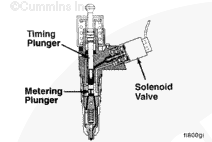
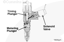
When this pressure reaches approximately 34,474 kPa [5000 psi], the needle valve begins to be forced upward.
Continued downward movement of the timing plunger and metering plunger results in steadily increasing fuel pressure. The result is that fuel is forced past the needle valve, through the spray holes, and into the combustion chamber.
Injection continues until the spill passage of the metering plunger passes the metering spill port.
Metering chamber pressure drops rapidly, allowing the needle valve to close abruptly. This action results in a positive end of injection. The positive end of injection prevents dribble and results in cleaner burning.
It is also at this point that the pressure relief valve “pops off”, thereby reducing the effects of the high-pressure “spike” that occurs at the time of the metering spill.
Hello, I'm Jack, a diesel engine fan and a blogger. I write about how to fix and improve diesel engines, from cars to trucks to generators. I also review the newest models and innovations in the diesel market. If you are interested in learning more about diesel engines, check out my blog and leave your feedback.
View all posts by Jack

;)
;)
;)
;)
;)
;)
;)
;)
;)
;)
;)
;)
;)
;)
;)
;)
;)
;)
;)
;)
;)
;)
;)
;)
;)
;)
;)
;)
;)
;)
;)
;)
;)
;)
;)
;)