ISM, ISMe, and QSM11 – 008-069   Wiring Harness, Cummins Electric Fan Clutch

General Information

TOC

This procedure applies to engines using an electric fan clutch controlled by the ECM and utilizing a Cummins® electric fan clutch wiring harness. If the wiring harness is not a Cummins® electric fan clutch wiring harness, refer to the OEM service manual for the correct troubleshooting procedure.

SMALL | MEDIUM | LARGE

Initial Check

TOC

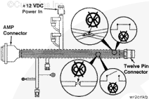
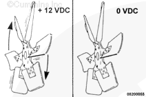
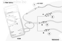
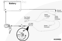
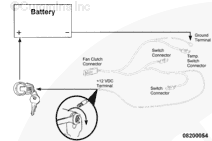
For the fan to operate, the Cummins® electromagnetic fan clutch relay must receive a 12-VDC signal from the ECM to engage and a 0-VDC signal from the ECM to disengage the fan clutch. Be sure the correct electrical connections have been made.

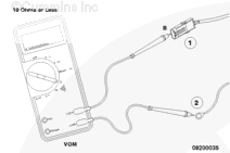
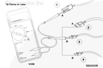
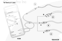
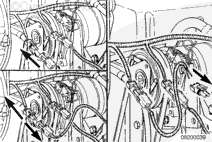
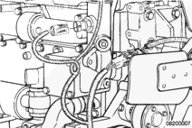
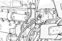
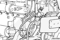
Inspect the wires and harness to be sure none are broken or shorted. Replace the harness or wires that are broken.

SMALL | MEDIUM | LARGE


The fan clutch will engage when it receives 12-VDC from the fan clutch relay and disengage when it receives 0- VDC from the fan clutch relay.

SMALL | MEDIUM | LARGE


The 12-VDC is supplied from the vehicle’s electrical system to the fan by one of three possible controls:

  • The manual fan on/off switch (1) in the cab
  • The refrigerant compressor pressure switch (2)
  • The temperature switch (3) in the thermostat housing.

SMALL | MEDIUM | LARGE


To check to be sure there are no open circuits, the continuity must be checked between the following pins of the wiring harness:

  • Pin B of the fan clutch connector (1) and the ground terminal (2)

SMALL | MEDIUM | LARGE


  • Pin A of the fan clutch connector (1) and the following fan harness connectors:
  • Pin A of the temperature switch connector (2)
  • Pin B of the refrigerant compressor pressure switch connector (3)
  • Pin B of the manual on/off cab switch connector (4).

SMALL | MEDIUM | LARGE


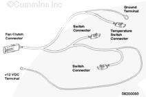
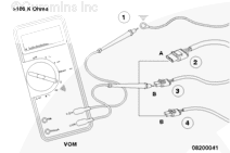
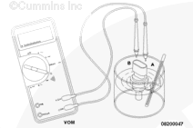
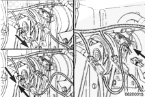
  • The positive (+) 12-VDC terminal (1) and the following fan harness connectors:
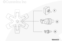
  • Pin B of the temperature switch connector (2)
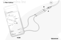
  • Pin A of the refrigerant compressor pressure switch connector (3)
  • Pin A of the manual on/off cab switch connector (4).

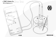
The multimeter must read a closed circuit (10 ohms or less). Repair or replace the harness if more than 10 ohms is detected on any of the above checks.

SMALL | MEDIUM | LARGE


Check for short circuits in the harness. The resistance must be greater than 100K ohms for the following:

  • Pin A of the fan clutch connector (1) to the ground terminal (2)

SMALL | MEDIUM | LARGE


  • The ground terminal (1) and the following fan harness connectors:
  • Pin A of the temperature switch connector (2)
  • Pin B of the refrigerant compressor pressure switch connector (3)
  • Pin B of the manual on/off cab switch connector (4).

SMALL | MEDIUM | LARGE


  • The positive (+) 12-VDC terminal (1) to the ground terminal (2)

SMALL | MEDIUM | LARGE


  • The positive (+) 12-VDC supply (1) and the following fan harness connectors:
  • Pin A of the temperature switch connector (2)
  • Pin B of the refrigerant compressor pressure switch connector (3)
  • Pin B of the manual on/off cab switch connector (4).

SMALL | MEDIUM | LARGE


  • Pin A of each of the three switch connectors (1) to pin B of each of the three switch connectors (1).

The harness must be repaired or replaced if any of the above resistances are less than 100 ohms.

SMALL | MEDIUM | LARGE


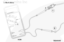
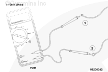
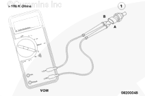
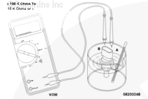
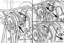
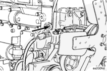
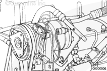
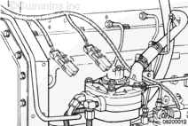
To check the temperature switch (1) for proper operation, check the continuity from pin A to pin B at room temperature ( must be greater than 100 ohms). Replace the switch if the resistance is less than 100K ohms.

SMALL | MEDIUM | LARGE


To check the temperature switch for operation at the fan ON temperature, place the probe (1) in a container of water, along with a thermometer.

 
SMALL | MEDIUM | LARGE


Place the multimeter probes in pin A and pin B.

 
SMALL | MEDIUM | LARGE


Heat the water.

Note the temperature at which the resistance changes from 100 or greater ohms to 10 ohms or less.

SMALL | MEDIUM | LARGE


If the switch does not close at the temperature required according to the switch manufacturer, the switch must be replaced.

 
SMALL | MEDIUM | LARGE


To check the freon compressor pressure switch and the manual fan on/off cab switch, refer to the manufacturer’s recommendations.

SMALL | MEDIUM | LARGE
   

Remove

TOC

Disconnect the operator-controlled manual switch harness, if used, from the base harness.

SMALL | MEDIUM | LARGE


Remove the refrigerant pressure switch harness from the base harness.

SMALL | MEDIUM | LARGE


Disconnect the gray harness connector from the temperature switch in the thermostat housing.

SMALL | MEDIUM | LARGE


Disconnect the large ring terminal with the black wire from the chassis ground.

SMALL | MEDIUM | LARGE


Disconnect the small ring terminal from the power source.

SMALL | MEDIUM | LARGE


Disconnect the fan clutch connector on the base harness from the fan clutch.

SMALL | MEDIUM | LARGE
   

Install

TOC

Connect the fan clutch connector on the base harness to the fan clutch.

SMALL | MEDIUM | LARGE


Connect the small ring terminal with the red wire to an ignition switch-controlled fused power source.

SMALL | MEDIUM | LARGE


Connect the large ring terminal with the black wire to the chassis ground.

SMALL | MEDIUM | LARGE


Install the coolant temperature switch in the thermostat housing, if it was removed.

SMALL | MEDIUM | LARGE


Connect the gray harness connector to the temperature switch in the thermostat housing.

SMALL | MEDIUM | LARGE


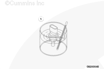
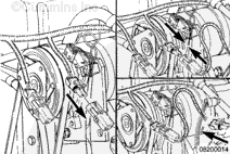
On air-conditioned vehicles, install the appropriate refrigerant pressure switch into the compressor outlet side of the refrigerant circuit, if it was removed.

SMALL | MEDIUM | LARGE


Connect the switch harness to the base harness and to the refrigerant pressure switch.

SMALL | MEDIUM | LARGE


Connect the operator-controlled manual switch harness to the base harness.

SMALL | MEDIUM | LARGE


Leave the base harness switch connector sealing cap(s) in place if a refrigerant pressure switch or an operator-controlled manual switch is not used.

SMALL | MEDIUM | LARGE
Last Modified:  23-Jan-2009