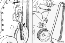
Install a new belt over the pulleys while holding the tensioner back. Be careful not to damage the belt while working it over the flanged pulleys.
Release the tensioner, and remove the breaker bar.
Belt drive systems equipped with an automatic belt tensioner can not be adjusted. A belt tension gauge will not give an accurate measure of the belt tension. The automatic belt tensioner is designed to maintain the proper belt tension over the life of the belt. Only an inspection of the tensioner is required.
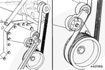
The belt tensioner is designed to operate within the limit of arm movement provided by the cast stops when the belt length and geometry are correct.
If the tensioner is hitting either of the limits during operation, check the mounting brackets and belt length. Loose brackets, bracket failure, alternator movement, incorrect belt length, or belt failure can cause the tensioner to hit the limits.
NOTE: A belt is considered used if it has been in operation for ten minutes or longer.
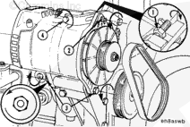
Install a new belt on the water pump and alternator pulleys. To prevent damage, do not roll a belt over the pulley or pry on it with a tool.
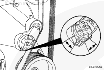
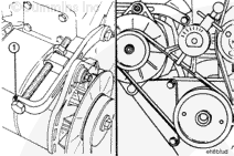
Turn the adjusting screw (1) clockwise to increase the belt tension.
Use belt tension gauge, Part Number ST-1293, or equivalent, to measure the belt tension. Refer to Procedure 018-005 in Section V for the correct tension value for the belt that is installed.
Belt drive systems equipped with an automatic belt tensioner can not be adjusted. A belt tension gauge will not give an accurate measure of the belt tension. The automatic belt tensioner is designed to maintain proper belt tension over the life of the belt. Only inspection of the tensioner is required.
The belt tensioner is designed to operate within the limit of arm movement provided by the cast stops, when the belt length and geometry are correct.
If the tensioner is hitting either of the limits during operation, check the mounting brackets and the belt length. Loose brackets, bracket failure, alternator movement, incorrect belt length, or belt failure can cause the tensioner to hit the limits.
Hello, I'm Jack, a diesel engine fan and a blogger. I write about how to fix and improve diesel engines, from cars to trucks to generators. I also review the newest models and innovations in the diesel market. If you are interested in learning more about diesel engines, check out my blog and leave your feedback.
View all posts by Jack


;)
;)
;)
;)
;)
;)
;)
;)
;)
;)
;)
;)
;)
;)
;)
;)