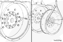
This component or assembly weighs greater than 23 kg [50 lb]. To prevent serious personal injury, be sure to have assistance or use appropriate lifting equipment to lift this component or assembly.
Remove the vehicle driveline and transmission. Refer to the OEM service manual.
Remove the clutch discs and pressure plate. Refer to the OEM service manual.
NOTE: If a clutch is used in the equipment, the threads in the clutch pressure plate mounting capscrew holes can be metric or standard. Be sure to use the correct capscrews.
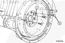
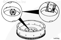
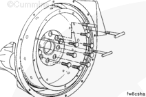
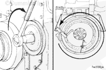
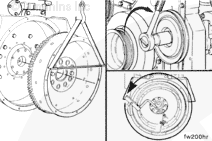
Determine the capscrew thread design and size, and install two “t-handles” in the flywheel (at points 4 and 5).
Remove the remaining seven flywheel mounting capscrews.
This component or assembly weighs greater than 23 kg [50 lb]. To prevent serious personal injury, be sure to have assistance or use appropriate lifting equipment to lift this component or assembly.
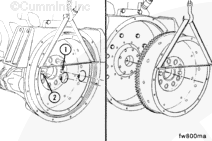
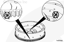
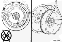
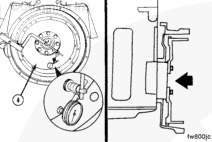
Tighten capscrews (1 and 2) in alternating sequence to loosen the flywheel.
When using a steam cleaner, wear safety glasses or a face shield as well as protective clothing. Hot steam can cause serious personal injury.
WARNING
When using solvents, acids or alkaline materials for cleaning, follow the manufacturer’s recommendations for use. Wear goggles and protective clothing to reduce the possibility of personal injury.
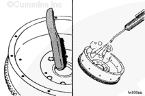
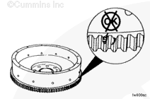
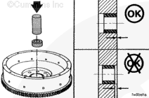
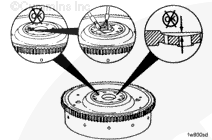
Use a wire brush to clean the crankshaft pilot bore.
Use steam or solvent to clean the flywheel. Dry with compressed air.
This component or assembly weighs greater than 23 kg [50 lb]. To prevent serious personal injury, be sure to have assistance or use appropriate lifting equipment to lift this component or assembly.
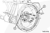
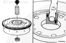
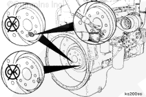
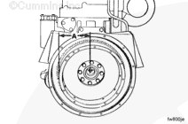
Install guide pin, Part Number 3376696, in the crankshaft flange.
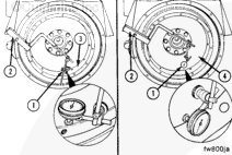
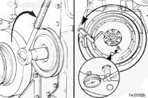
Use dial indicator gauge (1), Part Number 3376050 or equivalent, and dial gauge attachment (2), Part Number ST-1325, to inspect the flywheel bore (3) and face (4) runout.
Install the attachment to the flywheel housing.
Install the gauge on the attachment.
Install the contact tip of the indicator against the inside diameter of the flywheel bore.
This component or assembly weighs greater than 23 kg [50 lb]. To prevent serious personal injury, be sure to have assistance or use appropriate lifting equipment to lift this component or assembly.
Remove the flywheel if the total indicator reading is greater than the specification.
This component or assembly weighs greater than 23 kg [50 lb]. To prevent serious personal injury, be sure to have assistance or use appropriate lifting equipment to lift this component or assembly.
Install the flywheel and inspect the bore runout again.
This component or assembly weighs greater than 23 kg [50 lb]. To prevent serious personal injury, be sure to have assistance or use appropriate lifting equipment to lift this component or assembly.
Replace the flywheel if the runout does not meet specifications.
This component or assembly weighs greater than 23 kg [50 lb]. To prevent serious personal injury, be sure to have assistance or use appropriate lifting equipment to lift this component or assembly.
Install the clutch discs, pressure plate, transmission, and driveline, if equipped, in reverse order of removal. Refer to the OEM service manual.
Align the universal joints on each end of the driveshaft to prevent vibration.
Operate the engine and check for proper operation.
Hello, I'm Jack, a diesel engine fan and a blogger. I write about how to fix and improve diesel engines, from cars to trucks to generators. I also review the newest models and innovations in the diesel market. If you are interested in learning more about diesel engines, check out my blog and leave your feedback.
View all posts by Jack
 WARNING


;)
;)
;)
;)
;)
;)
;)
;)
;)
;)
;)
;)
;)
;)
;)
;)
;)
;)
;)
;)
;)
;)
;)
;)
;)
;)
;)
;)
;)
;)
;)
;)
;)
;)
;)
;)
;)
;)
;)
;)
;)
;)