These instructions are for a single unit drive shaft, which attaches to the engine and transmission with flange mount U-joints. Some marine engines are equipped with drive shafts that are various lengths, depending on the boat builder design. This allows the engine to be mounted some distance from the propulsion system drives. The drive system discussed in this procedure is the Pod drive shaft. This procedure will cover removal, alignment, and installation.
Batteries can emit explosive gases. To reduce the possibility of personal injury, always ventilate the compartment before servicing the batteries. To reduce the possibility of arcing, remove the negative (-) battery cable first and attach the negative (-) battery cable last.
This component or assembly weighs greater than 23 kg [50 lb]. To prevent serious personal injury, be sure to have assistance or use appropriate lifting equipment to lift this component or assembly.
NOTE: The longer drive shafts can be very heavy. The technician should consider whether two technicians are needed for the procedure.
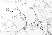
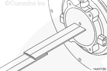
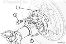
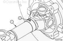
Back out the capscrews (1) from each end of the drive shaft (2). Support the shaft while removing the last capscrew from each end. Set the drive shaft to one side.
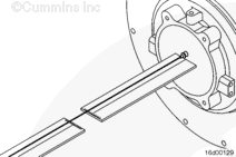
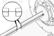
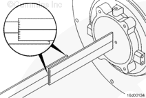
Rotate both tools 90 degrees so they are perpendicular to the ground.
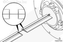
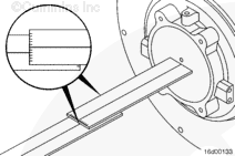
Read the angles of the pod and engine where the lines cross the scales at the free end of the blades. This gives the operator the vertical angles of the engine and pod. The readings on both scales should be very close to the same.
This component or assembly weighs greater than 23 kg [50 lb]. To prevent serious personal injury, be sure to have assistance or use appropriate lifting equipment to lift this component or assembly.
NOTE: The longer driveshafts can be very heavy. The technician should consider whether two technicians are needed for this procedure.
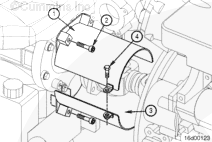
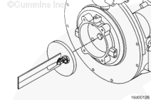
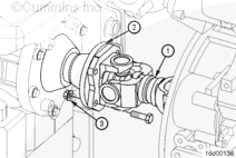
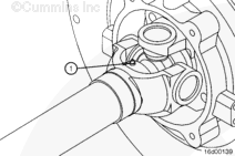
Fully collapse (push) the splined portion of the driveshaft (1) together.
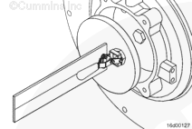
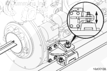
Use flange bolt (3/8-24, 1-1/2 in long). Attach the driveshaft to the transmission input shaft flange (2).
NOTE: These bolts can not be used on the opposite side of the drive shaft because they will bottom out.
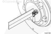
Tighten the eight locknuts (3) on the four transmission input shaft flange bolts.
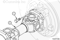
Lubricate the driveshaft slip-joint (1) through the grease fitting (2) by applying approximately three to six pumps of specified grease from a typical hand-operated grease gun.
Use Mercury™ Engine Coupler Spline Grease, Part Number 92-802869A1, or equivalent.
Batteries can emit explosive gases. To reduce the possibility of personal injury, always ventilate the compartment before servicing the batteries. To reduce the possibility of arcing, remove the negative (-) battery cable first and attach the negative (-) battery cable last.
Hello, I'm Jack, a diesel engine fan and a blogger. I write about how to fix and improve diesel engines, from cars to trucks to generators. I also review the newest models and innovations in the diesel market. If you are interested in learning more about diesel engines, check out my blog and leave your feedback.
View all posts by Jack

 WARNING


;)
;)
;)
;)
;)
;)
;)
;)
;)
;)
;)
;)
;)
;)
;)
;)
;)
;)
;)
;)
;)
;)
;)
;)
;)
;)
;)
;)
;)
;)
;)
;)
;)
;)
;)
;)
;)
;)
;)
;)