Specifications
|
TOC |
Marine Applications
Starting Motor Circuit:
Maximum resistance:
| 12-VDC |
0.00075 ohm |
| 24-VDC |
0.002 ohm |
Starting Motor Circuit:
Maximum Voltage Drop:
| 12-VDC |
1.95-VDC |
| 24-VDC |
1.7-VDC |
Marine Applications
Unaided Cold Start:
| Maximum Ambient Temperature |
-7°C [19°F] |
| Minimum Cranking Speed Required |
120 rpm |
Industrial Applications
Starting Motor Circuit:
Maximum resistance:
| 12-VDC |
0.00075 ohm |
| 24-VDC |
0.002 ohm |
Starting Motor Circuit:
Maximum Voltage Drop:
| 12-VDC |
1.95-VDC |
| 24-VDC |
1.7-VDC |
Industrial Applications
Unaided Cold Start:
| Maximum Ambient Temperature |
-12°C [10°F] |
| Minimum Cranking Speed Required |
120 rpm |
Generator Drive Applications
| Minimum Ambient Temperature for Cold Start With Coolant Heated to Rated Speed |
-14°C [7°F] |
| Minimum Ambient Temperature for Unaided Cold Start to Low Idle Speed |
-4°C [25°F] |
| Minimum Ambient Temperature for NFPA 110 Cold Start (90°F minimum coolant temperature) |
0°C [32°F] |
Minimum recommended battery capacity:
|
System Voltage
|
Ambient Temperature
|
|
-18°C [0°F]
|
0°C [32°F]
|
|
Cold Cranking Amperes
|
ReserveCapacity1Minutes
|
Cold Cranking Amperes
|
ReserveCapacity1Minutes
|
|
12-VDC
|
1800
|
640
|
1280
|
480
|
|
24-VDC2
|
900
|
320
|
640
|
240
|
- The number of plates within a given battery size determines reserve capacity. Reserve capacity determines the length of time that sustained cranking can occur.
- Cold Cranking Amperes rating are based on two 12-VDC batteries in series.
|
For automotive applications a minimum of 9-VDC at the power connector is required to power up to the ECM. For Industrial, Power Generation, and Marine Applications a minimum of 6.5-VDC at the power connector is required to power up the ECM.
|
Batteries (Specific Gravity)
|
TOC |
|
Specific Gravity at 27°C [81°F]
|
State of Charge
|
|
1.260 to 1.280
|
100%
|
|
1.230 to 1.250
|
75%
|
|
1.200 to 1.220
|
50%
|
|
1.170 to 1.190
|
25%
|
|
1.110 to 1.130
|
Discharged
|
|
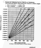
Maximum Resistance of Starting Motor Circuit
12-VDC Starting Motor (Ohm) 0.00001
24-VDC Starting Motor (Ohm) 0.00020
Cable resistances can be obtained in the accompanying Battery Cable Resistance Chart. If the frame is in ground circit the frame length must be considered cable of the same size as that used in the balance of the system.
|
Item
|
Resistance Ohms
|
|
Connection
|
0.00001
|
|
Additional Contacter (Series-Parellel Switch, Relays, etd.)
|
0.00020
|
|
|
|
|
|
|
Last Modified: 06-Feb-2009
Published by Jack
Hello, I'm Jack, a diesel engine fan and a blogger. I write about how to fix and improve diesel engines, from cars to trucks to generators. I also review the newest models and innovations in the diesel market. If you are interested in learning more about diesel engines, check out my blog and leave your feedback.
View all posts by Jack
;)
;)