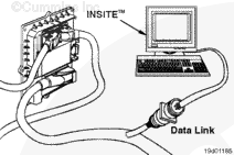
Connect an electronic service tool to the vehicle’s datalink.
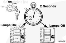
Turn the keyswitch to the ON position.
Select the monitor mode on the electronic service tool. The electronic service tool must be able to communicate with the ECM. If the ECM will not communicate with the service tool, refer to the Communication Error – Electronic Service Tool or Control Device symptom tree in Section TS.
NOTE: Record all programmable parameters, features, and calibration data from the old ECM before disconnecting the harness connectors. This data will be needed to program the new ECM.
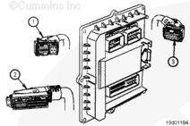
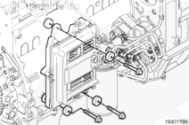
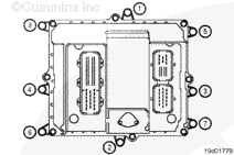
Disconnect the 36-pin engine harness (1), 89-pin OEM harness (2), and the 16-pin engine harness (3) connectors from the ECM.
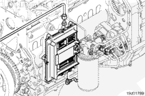
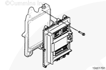
Remove the three cooling plate mounting capscrews. Do not
lose any of the vibration isolators or the ECM ground strap. The vibration isolators are on both sides of the cooling plate. The ECM ground strap is on the cooling plate side only.
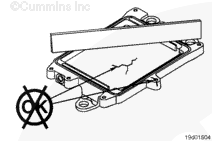
Do not paint the cooling plate. Make sure there is no grease or dirt between the ECM and the cooling plate. Otherwise, debris can get into the fuel system.
Install the ECM onto the cooling plate.
Tighten the three capscrews only enough to secure the ECM to the cooling plate.
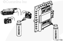
To reduce the possibility of ECM damage, do not blow compressed air into the ECM ports or connectors. Compressed air can contain moisture due to condensation.
Use quick-dry electrical contact cleaner, Part Number 3824510, to remove all dirt and moisture from the ECM connector ports and harness connectors.
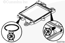
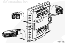
Connect the OEM and engine harness connectors to the ECM. The engine harness connectors and the OEM harness connector have an arm on the connector that will snap down on itself when properly connected to the ECM.
NOTE: When an ECM is replaced, the new ECM must be calibrated. Refer to Procedure 019-032.
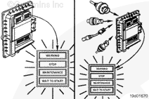
Verify that the indicator lamps (WARNING, STOP, MAINTENANCE and WAIT TO START) illuminate for approximately 2 seconds and then go off, one after the other.
The above-described sequence of indicator light illumination and shutoff verifies that the ECM is receiving power and powering up correctly.
Hello, I'm Jack, a diesel engine fan and a blogger. I write about how to fix and improve diesel engines, from cars to trucks to generators. I also review the newest models and innovations in the diesel market. If you are interested in learning more about diesel engines, check out my blog and leave your feedback.
View all posts by Jack


 CAUTION

;)
;)
;)
;)
;)
;)
;)
;)
;)
;)
;)
;)
;)
;)
;)
;)
;)
;)
;)
;)
;)
;)
;)
;)