To reduce the possibility of damage to the connector pins, do not use probes or leads other than Part Numbers 3164110 and 3164112. The leads must fit tightly in the connector without expanding the pins of the connector.
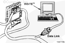
If INSITE™ is available, monitor the switched road speed governor limit switch circuit for proper operation. If
not, follow the troubleshooting procedures in this section.
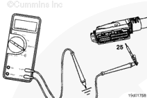
Insert a test lead into pin 25 of the OEM harness connector, and attach it to a multimeter probe. Touch the other multimeter probe to the engine block ground.
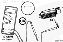
Move the switched road speed governor limit switch to the ON position. The multimeter
must show a closed circuit (10 ohms or less). If the circuit is
not closed, inspect wire number 25 for an open circuit. Refer to the OEM troubleshooting and repair manual. If the resistance is within specification, wire number 25
must be checked for a short circuit to ground, a short circuit from terminal to terminal, and a short circuit to an external voltage source.
Isolate the switched road speed governor limit switch circuit.
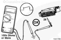
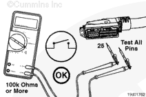
Insert a test lead into pin 25 of the OEM harness connector, and attach it to the multimeter probe. Touch the other multimeter probe to the engine block, and measure the resistance.
must show an open circuit (100k ohms or more). If the circuit is
not open, there is a short circuit to ground in the switched road speed governor limit switch circuit, provided that the switch has been previously checked.
Repair or replace the wire connected to pin 25 according to the vehicle manufacturer’s instructions.
Isolate the switched road speed governor limit switch circuit.
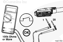
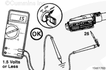
Insert one of the test leads into pin 25 of the OEM harness connector. Insert the other test lead into pin 1 of the connector. Connect the alligator clips to the multimeter probes. Measure the resistance.
If the voltage value is more than 1.5 VDC, there is a short circuit between the wire connected to pin 25 and a wire carrying power in the OEM harness. Repair the OEM harness according to the vehicle manufacturer’s procedures.
Connect all components after completing the repairs.
Hello, I'm Jack, a diesel engine fan and a blogger. I write about how to fix and improve diesel engines, from cars to trucks to generators. I also review the newest models and innovations in the diesel market. If you are interested in learning more about diesel engines, check out my blog and leave your feedback.
View all posts by Jack

 CAUTION





;)
;)
;)
;)
;)
;)
;)
;)
;)
;)
;)
;)
;)
;)