 |

Engine Protection System |
|||||||
Depending on how the engine protection feature is set up, the engine protection system will initiate an engine shutdown and prevent an engine restart from the following set points:
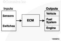
Setup Information The engine protection feature monitors critical system temperatures, pressures, and fluid levels. This feature requires minimal setup by the user. Individual sensor engine protection limits and states are preset in the calibrations and are not adjustable by the electronic service tool. Engine protection shutdown and engine protection restart are adjustable with the electronic service tool. Engine Protection Shutdown When engine protection shutdown is enabled using the electronic service tool, it can cause the engine to shut down when an engine parameter becomes critically out of range. This feature can be enabled or disabled using the electronic service tool. The engine can be restarted after an automatic shutdown, in order to move the vehicle to a safe location. The engine will continue to monitor engine parameters and another shutdown will occur when an engine parameter becomes critically out of range. Engine Protection Restart Restart derate prevents the user from defeating an active torque or speed derate. If the user stops and restarts the engine, the torque or speed derate will still be active. Engine Protection Shutdown Override When engine protection shutdown override is enabled using the electronic service tool, it will allow the operator to override an impending engine shutdown caused by the engine protection feature. The intended market for this feature is transit applications, such as buses, that possibly need to move the vehicle to a safe location before engine shutdown takes effect. To override engine protection shutdown, the operator depresses an OEM-supplied button during the 30-second engine protection warning period (WARNING lamp flashes). This will restart the 30-second shutdown warning timer, giving the driver an extra 30 seconds to move the vehicle to a safe location. Each time the button is depressed, the 30-second warning period is restarted. Detailed Operation and Interaction Information The engine protection feature provides protection against progressive engine damage by comparing data gathered at engine protection sensors and calibrated minimum and maximum limits. If a value is found to be out-of-range, an engine protection fault code is recorded. The engine protection feature is not adjustable with the electronic service tool. The engine protection derate can occur in two ways:
Engine protection values are stored in the electronic control module (ECM) every time an engine protection fault code is set. The engine protection shutdown, engine position restart, and engine position shutdown override are adjustable with the electronic service tool.
|
|||||||
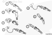
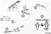
QST30 System Components |
|||||||||||||||||||||||||||||||||||||||||||||||||||||||
|
Accelerator Interlock The accelerator interlock feature is intended to keep the engine at idle speed by using an interlock switch that is usually attached to the vehicle’s door. Most buses use this feature to disable the accelerator pedal and PTO operation while the bus door is open; thus the engine remains idle while the door is open. Setup Information For this feature to function, an interlock switch must be installed. The electronic control module (ECM) always has this feature enabled, but it must have the interlock switch input to activate the feature. Detailed Operation and Interaction Information This feature disables the cab accelerator pedal and PTO operation while the interlock switch input to the ECM is closed (door is open). Once the interlock switch is opened, the ECM allows accelerator and PTO inputs to control the engine speed. Due to different customer needs, each particular manufacturer will select the interaction with its brakes, transmission, and fast- and slow-idle selection capabilities. Altitude Derate At high altitudes, the turbocharger can exceed its design limit if achieving typical boost pressure(s). The air is less dense and can cause the turbocharger to overspeed; therefore, the electronic control module (ECM) derates the fueling to limit exhaust flow. The ECM uses the ambient air pressure sensor to determine when to derate fueling. The fueling derate starts to occur when the engine is operated 3048 m [10,000 ft] above sea level. Setup Information This feature is a basic feature in the calibration. It is not customer adjustable.
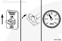
Exhaust Brake Control
The exhaust brake control feature is used for control of the exhaust brakes that slow engine speed during motoring conditions.
Fuel Heater Control The fuel heater is located on the fuel filter head and is used to heat the fuel to prevent gelling and waxing during very cold ambient conditions. The electronic control module (ECM) monitors the fuel temperature and controls the fuel heater driver. This relay controls the fuel heater. Below a set temperature, the heater will be turned on; above a set temperature, the heater will be turned off. Setup Information The fuel heater control feature is calibration dependent. It is not customer adjustable. Detailed Operation and Interaction Information See table for heater details.
Intake Air Heater Control
The intake air heater control feature controls the heating elements located in the engine’s intake air system. Starting the engine and white smoke control are enhanced by the use of an intake air heater. The electronic control module
Setup Information The intake air heater(s) control feature is calibration dependent. It is not customer adjustable. Detailed Operation and Interaction Information Depending on system voltage, the equipment can have one or two intake air heater(s):
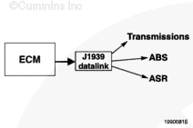
The heaters are controlled by the ECM via a relay connected to the battery supply. The OEM is responsible for wiring and mounting the relays. J1939 Datalink The electronic control module (ECM) communicates with electronic service tools and other vehicle controllers, such as transmissions, antilock braking system, automatic slip reduction, and electronic dashboards, through an SAE J1939 datalink. Some vehicles and equipment will have J1939 networks on them that link many of the electronic controllers together. Vehicle control devices can temporarily command engine speed or torque to perform one of its functions, such as transmission shifting or antilock braking. Torque History Recorder Engine torque history is an audit trail displaying dataplate data for calibrations and programmable power selections. This is a read only screen to display what maximum horsepower and torques the engine can produce with installed calibrations and codes. Setup Information Engines have the ability to produce more torque than required. It is possible to adjust an engine to produce more torque and power than the drivetrain and cooling package are designed to handle. The audit trail of engine torque history is useful when determining the potential causes of driveline- or overheat-related failures. Trip Information The trip information system constantly monitors and records various engine and operating data necessary to track both engine and driver/operator performance. The data can be viewed using the electronic service tool. If any faults occur that can corrupt the trip data, the system will caution the user when viewing the data. Setup Information The trip information system constantly monitors and records various engine and operating data necessary to track both engine and driver/operator performance.
Detailed Operation and Interaction Information Trip information can provide data relative to operation of the engine and performance of the driver. Trip information is available in the following ways:
Water-In-Fuel Warning The water-in-fuel sensor protects fuel system by alerting the driver/operator that water has accumulated in the fuel-water separator and needs to be drained. The vehicle operator will be warned of a water-in-fuel condition by illuminating the MAINTENANCE lamp. Setup Information The ISB four-cylinder and ISB e four- and six-cylinder engines will not have this sensor in the bottom of the engine mounted fuel filter. The fuel-water separator and water-in-fuel sensor will be located off the engine in an OEM-specific location. Detailed Operation and Interaction Information The fuel-water separator removes emulsified and free water from the fuel as it passes through the filter media. The removed water is heavier than the fuel and falls to the bottom of the filter canister where it accumulates.
|
|||||||||||||||||||||||||||||||||||||||||||||||||||||||
 WARNING
Programmable Features |
|||||||||||||||||||||||||||||||||||||||||||||||||||||||||||||||||||||||||||||||||||||||||||||||||||||||||||||||||||||||||||||||||||||||||||||||||||||||||||||||||||||||||||||||||||||||||||||||||||||||||||
|
Alternator Failure Warning This feature is designed to track battery voltage and provide early warning if the voltage level falls outside upper and lower limits for a certain period of time. Both limits and time period are calibrated values. Each warning level has an associated fault code and fault lamp. The three voltage warning levels are:
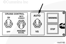
Detailed Operation and Interaction Information Battery voltage monitor (enable/disable) Monitors the battery voltage input to the electronic control module (ECM) and warns the operator of high, low, or very low voltage system errors. When selected, the vehicle system voltage must be set accordingly to set thresholds for warnings appropriately. Also, idle speedup can be enabled to allow the engine to be controlled to a higher idle speed to maintain battery voltage. Vehicle system voltage (12 or 24 VDC) Indicates the voltage system (12 or 24 VDC) being used on the vehicle. The voltage system warning levels will then be set accordingly. Idle speedup (enable/disable) Increases the idle speed whenever a low or very low system voltage level is detected. The idle speed is increased in an effort to raise the system voltage to a normal level. When idle speedup is active, the idle decrement switch is disabled to prevent the operator from defeating the idle speedup. There are two parameters that track the duration and number of idle speedup events. Automotive and Variable Speed Governor (VS) Accelerator Types and Cab Switchable Governor The accelerator-type feature gives the owner a choice of two engine governors:
The automotive governor allows a larger speed variation under varying load conditions given a throttle position (engine speed varies with load). The variable speed (VS) governor maintains a constant engine speed for a given throttle position under varying load conditions. Setup Information The accelerator-type feature allows the user to choose between two governor types. The selection of governor types can be accomplished by way of a cab-mounted accelerator selection switch. If the cab is not equipped with this switch, then the accelerator type can be selected with the electronic service tool.
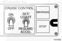
Cruise Control
Cruise control maintains vehicle speed at a driver selectable mph. With cruise control, vehicle speed control is more precise, resulting in improved fuel economy. It is similar to an automobile cruise control where the driver/operator has the ability to adjust and maintain a desired road speed.
Setup Information In order for the cruise control feature to activate, vehicle speed must be greater than 30 mph, service brake and clutch pedal must be released, engine speed must be above low idle, and there must be no active vehicle speed sensor (VSS) faults. In order to set and adjust cruise control speed according to the dash switch nomenclature, the switch usage/configuration parameter must Cruise control can be deactivated by turning the cruise control switch to the OFF position. Any one of the following conditions will result in cruise control reverting to standby mode:
The three operation modes include off, standby, and active. These are determined by the switch positions of the on/off switch and the set/resume switch. The cruise control on/off switch allows the driver to turn the feature on and off. The set/resume switch allows the driver to set, resume, or adjust the set vehicle speed (increase or decrease of mph). Off Mode When the cruise control switch is in the OFF position, cruise control does not affect engine operation, nor can it be activated. Standby Mode When the cruise on/off switch is in the ON position, cruise control will remain on standby until a request for activation is made by the driver using the cruise set/resume switch. Active Mode If the driver activates cruise control by using the set position of the set/resume switch; then the cruise control will maintain the vehicle speed at that set vehicle speed. When the driver activates cruise control by using the resume position of the set/resume switch, the engine will then maintain vehicle speed at the last set vehicle speed the driver commanded. Set/Resume Switch Usage – This parameter reverses the switch throw for certain functions of the set/resume switch. This parameter can be programmed using an electronic service tool. The set/resume switch accesses functions for cruise control, the PTO feature, road speed governor, idle governor, and diagnostics. There are two selections: Set/accel or set/coast. Depending on the selection, the set and resume positions correspond to the switch functions defined in the following table.
Detailed Operation and Interaction Information The following parameters can tailor the cruise control operation to the driver’s preference. Cruise Control Save Set Speed This is a programmable feature that, when enabled, allows the cruise control set speed to be saved in the electronic control module (ECM) memory after the keyswitch is turned to the OFF position. When the engine is restarted and the cruise control switch is turned to the ON position, the resume function can be used to resume the vehicle speed to that of the last set speed prior to turning the keyswitch to the OFF position without first utilizing the set function. Cruise Control Autoresume This feature allows gearshifts while in cruise control without the need to resume cruise control once the shift is complete. In order for this feature to function properly, the shift must be initiated with the clutch, the shift must take no longer than 6 seconds, and once the shift is complete, engine speed must be greater than low idle and vehicle speed must be greater than 30 mph. If a manual, Top 2™, or partially automated transmission is installed and autoresume is desired, then the autoresume feature should be enabled. However, this feature is not intended for use with fully automated transmissions. Maximum Cruise Control Speed This adjustable parameter defines the maximum vehicle speed that can be selected when the cruise control feature is operating. Setting the maximum cruise control speed will result in better safety and fuel economy when trimmed appropriately. The maximum cruise control speed is independent of the accelerator maximum vehicle speed feature, but must be less than or equal to the maximum vehicle speed parameter. Exhaust Brake in Cruise Control (speed above cruise set speed for exhaust brake activation) This parameter can only be trimmed if exhaust brake in cruise control is enabled. This parameter allows exhaust braking at a speed equal to the set cruise control speed plus the speed above cruise set speed for exhaust brake activation. Refer to Programmable Features for Automatic Exhaust Brake Activation in Cruise Control in this section.
Cruise Control Switch Configuration This parameter tells the electronic control module (ECM) how the cab switch is configured. If it is set to YES, then the cab switch will be set/accel in one position and resume/coast in the other position. If it is set to NO, then set/coast will be in one position while resume/accel will be in the other position. The set/coast function would occur when the switch is up and resume/accel would occur when the switch is down. Engine Performance Maximum Switched Engine Speed The feature allows the user to program and select a maximum engine operating speed lower than the default maximum engine speed. This can be useful when the engine is driving a device that requires a lower maximum engine speed than the default maximum engine speed. For example, a particular application can have a hydraulic system that is only capable of being driven at speeds up to 1500 rpm, but there are times when the hydraulic system is disengaged and the higher engine speed is desirable. Using an OEM-installed switch, the operator can select between the default maximum engine speed and lower programmable maximum switched engine speed when necessary. NOTE: If a switch is not installed, the maximum engine speed will be limited to the default maximum switched engine speed.Engine Warm-up Protection The engine warm-up protection feature prevents internal engine damage by limiting engine speed and torque at start-up until adequate oil pressure is achieved. Setup Information This feature is enabled or disabled using the electronic service tool. Detailed Operation and Interaction Information This feature, when enabled, will activate after the keyswitch has been cycled and the vehicle speed is at 0 mph. When the engine is started, the engine warm-up feature will monitor the engine oil pressure and the feature will hold the engine speed at low idle or at a calibrated value (600 to 800 rpm) until adequate oil pressure is achieved and maintained. The accelerator pedal, alternate PTO, remote PTO, and other inputs can not adjust the engine speed while this feature is operating. If there is an active oil pressure or coolant temperature fault code or if oil pressure is never achieved or maintained, the engine warm-up protection feature will continue to operate until the fault code goes inactive or until engine protection becomes active. If the vehicle speed sensor (VSS) signal is lost, then the keyswitch cycle alone will activate the feature. When the keyswitch is in the OFF position and engine is shut down, an oil bleed-down timer is initiated. If the engine is started before this timer has run out, the feature will not operate during engine start-up. Exhaust Brake or Driveline Retarder Control This feature tells the electronic control module (ECM) whether an exhaust brake or a drivetrain retarder is being used on the vehicle. It allows the driveline retarder to operate below 1000 rpm down to idle speed, but will disengage at this speed when the exhaust brake feature is chosen. Automatic Exhaust Brake Activation in Cruise Control The exhaust brake control feature, when enabled with the electronic service tool, can be automatically activated during cruise control conditions. The cruise control set speed for exhaust brake activation must be enabled and a value set with the electronic service tool for this feature to operate automatically. For example, the cruise control set speed is set for 65 mph and the automatic exhaust brakes in cruise control is enabled with the cruise control set speed for exhaust brake activation set to 3 mph. When the vehicle is cruising at 65 mph and begins to go down a hill, the exhaust brakes will automatically activate at 68 mph. The operator can manually activate the exhaust brakes at any time as long as the activation requirements are met. Fan Control The electronic control module (ECM) can control the cooling fan based on inputs from the coolant temperature sensor and the intake manifold temperature sensor. Some applications will also provide inputs to the ECM for auxiliary device cooling (i.e., air conditioner pressure, power steering temperature, transmission temperature) or a manual fan switch for fan control. Several parameters are associated with the fan control and they are described below.
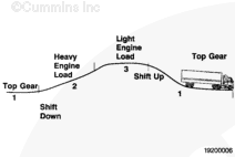
Gear-Down Protection Gear-down protection has two functions. It gives the driver the performance needed while driving one gear down from top gear and also yields improved fuel economy by increasing the time in top gear. Setup Information By requiring that the vehicle is in top gear before maximum road speed can be reached, the engine speed is kept in a more fuel efficient range. If the driver were allowed to drop down a gear and still maintain maximum road speed, the engine speed would be raised, causing the engine to run in a higher engine speed range with lower fuel economy. Gear-down protection is a method of improving fuel economy without negating performance by keeping the engine in fuel efficient engine speed range at maximum road speed, while balancing the need for power in one gear down from top gear. This feature can be enabled using the electronic service tool.
NOTE: There are several parameter dependencies associated with gear-down protection. The maximum vehicle speed and light engine load must be of equal or lesser value than maximum vehicle speed and heavy engine load, which
|
|||||||||||||||||||||||||||||||||||||||||||||||||||||||||||||||||||||||||||||||||||||||||||||||||||||||||||||||||||||||||||||||||||||||||||||||||||||||||||||||||||||||||||||||||||||||||||||||||||||||||||
|
Gear-Down Protection Light-Load Vehicle Speed This setting is in effect when the driver does not need to be in lower gears, as when driving in a steady-state condition on level ground. This trim must be set below the heavy engine load vehicle speed. By setting the trim this way, the driver will be penalized with a performance loss whenever unnecessarily driving in lower gears. Gear-Down Protection Heavy-Load Vehicle Speed The setting is in effect when the driver truly needs to be in lower gears, as when accelerating through the gears or climbing a grade. This trim must be set just below the maximum vehicle speed in top gear. By setting the heavy engine load this way, the driver will still have performance when needed. Example: With the maximum vehicle speed in top gear set at 62 mph, the driver can choose to set the heavy engine load at 60 mph and the light engine load at 55 mph. This will create a more significant performance penalty and will encourage the driver to use the top gear. |
 |
||
Gear-Down Protection in Lower Gears
When the vehicle transmission is operating in second gear-down or lower, the vehicle speed is limited depending on engine load. Under heavy-load conditions, vehicle speed is limited to the gear-down protection heavy-load vehicle speed minus 1 mph. Under high-load conditions, vehicle speed is limited to the gear-down protection light-load vehicle speed minus 3 mph.
Example: With the maximum vehicle speed at 62 mph, light-load vehicle speed set to 58 mph, and heavy-load vehicle speed set to 60 mph; in second gear-down, vehicle speed will be limited to 55 mph with light engine load and 59 mph with heavy engine load. This will encourage the driver to operate in a higher gear when possible.
In order to optimize gear-down protection for the maximum benefit of vehicle performance and fuel economy, the vehicle evaluation/vehicle mission simulation program is recommended. The vehicle evaluation/vehicle mission simulation is a software program that determines vehicle performance in gears based on engine and vehicle specifications (i.e., rear axle ratio and transmission type). Contact a Cummins Representative for more information on vehicle evaluation/vehicle mission simulation for your vehicle application.
Idle Governor and Adjustable Low Idle
The idle governor feature controls engine fueling to maintain the desired engine idle speed within the torque capability of the engine. Idle engine speed can be adjusted by operator inputs. The low-idle engine speed parameter is the speed at which the engine will idle. This speed can be adjusted by a cab switch if the switch is installed and the low-idle adjustment feature is enabled.
Setup Information
On engine start-up, the idle engine speed will be the idle reference speed. The idle reference speed is the largest value of the following speeds:
- The default idle engine speed
- The adjustment idle engine speed (if enabled) or
- Warm-up engine protection speed.
Idle Adjustment Switch
This feature, when enabled, allows the idle increment/decrement capability of the set/resume switch on the dash. The idle speed can be increased or decreased in 25-mph increments with the set/resume switch on the dash and the allowable adjustment range is 600 to 800 rpm.
Idle Shutdown
When the engine is at idle, this feature will automatically shut down the engine after a specified period of time depending on the mode of operation and customer-programmable parameters. This feature is intended to reduce engine idle time and increase the fuel economy.
Setup Information
The idle shutdown feature, when enabled, maintains a timer that only starts counting when the following conditions are met:
- When the engine operates at an idle state
- When the vehicle speed is zero
- When the service brake, clutch, and accelerator pedal are not depressed.
Idle Shutdown Time
This is the period of engine idling time when there is no activity from the driver, such as clutch, brake, or accelerator actuation before the engine automatically shuts off.
NOTE: The parameter will not appear if the idle shutdown feature is turned off.
Idle Shutdown in PTO
This feature automatically shuts off the engine after a period of PTO or remote PTO operation in which there is no activity from the driver, such as clutch, brake, or accelerator actuation.
Idle Shutdown Override
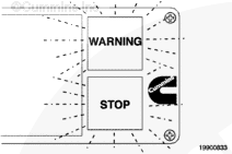
This feature allows the driver to override the idle shutdown by changing the position of the brake, clutch, or accelerator anytime during the idle shutdown warning period. The idle shutdown warning period lasts for 30 seconds prior to engine shutdown. The yellow WARNING lamp on the dash will flash during the idle shutdown warning period. After the idle shutdown feature has been overridden, this feature will not shut off the engine again until the vehicle has been moved.
J1939 Multiplexing (J1939 mux)
Multiplexing is the ability to send and receive messages simultaneously over a J1939 datalink instead of using hardwired connections. This is accomplished by utilizing a vehicle electronic control unit. Inputs from switches, status parameters, and sensors can be hardwired into the vehicle electronic control unit. The vehicle electronic control unit can then broadcast this information throughout a vehicle system. The electronic control module (ECM) on Cummins engines will be one recipient of this information.
Setup Information
The multiplexing feature is adjustable with the electronic service tool and controls all device enables listed. When disabled, multiplexing is not allowed into the ECM. When enabled, a various number of switches, status parameters, and sensors will or will not be multiplexed in the ECM via the J1939 datalink. These multiplexed inputs must be individually enabled.
Available inputs for multiplexing:
- Accelerator interlock switch
- Air conditioner pressure switch
- Service brake switch
- Clutch switch
- Cruise control on/off switch
- Cruise control resume switch
- Cruise control set switch
- PTO on/off switch
- PTO resume switch
- PTO set switch
- Idle increment/idle decrement switch
- Parking brake switch (layland only)
- Diagnostic switch/user-engaged snapshot
- Torque derate switch
- Manual fan switch
- Engine brake switch
- Accelerator pedal position
- Idle validation status – on/off idle
- Remote accelerator switch
- Remote accelerator position
- Tachograph
- Engine sensor readings
- Engine speed
- Indicator lamp status.
|
Maintenance Monitor NOTE: The maintenance monitor is designed to alert the operator of the need for a routine maintenance stop. Maintenance records must still be maintained for historical purposes.NOTE: The maintenance monitor uses data received from the vehicle speed sensor (VSS) to determine distance and data from the ECM to determine the amount of fuel burned. Whenever a VSS or battery voltage fault has occurred, the maintenance monitor data can be inaccurate.The maintenance monitor is an electronic program contained in the ECM for monitoring oil drain intervals. Benefits to the customer include the ability to track drain intervals automatically in one of three modes. The maintenance monitor can replace the standard manual methods for oil drain intervals. |

|
 |
|
Setup Information
The feature can be enabled with the electronic service tool and one of three modes can be selected:
- Automatic mode
- Distance mode
- Time mode.
Additionally, the customer is offered the provision for an interval alert percentage. The interval alert percentage is a value dependent upon the severity of operation of the application. This interval factor provides a direct relationship to the harshness of environment or severity of duty cycle.
 CAUTION CAUTION The use of synthetic-base oil does not justify extended oil change intervals. Extended oil change intervals can decrease engine life due to factors such as corrosion, deposits, and wear.
|
Automatic Mode
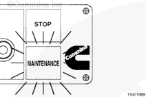
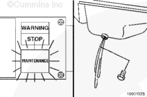
The automatic mode allows the ECM internal logic to decide when a drain interval is required. It will monitor distance traveled, hours of operation, and quantity of fuel consumed and equate these values against the severity of operation that the customer is requested to provide (interval factor). When automatic mode is selected, the severe oil drain interval duty cycle is the default. When logic deems it is time to change the oil, a MAINTENANCE lamp is illuminated in the cab for driver awareness. This lamp will continue to illuminate with each start-up until reset.
Distance and Time Modes
The distance and time modes are more direct methods of tracking. The customer can enter the distance between drain intervals or hours of operation between drain intervals directly. When limits are reached, the ECM will illuminate the in-cab MAINTENANCE lamp. This mode must not be selected for applications that do not have a vehicle speed sensor (VSS).
Interval Alert Percentage
The interval alert percentage allows the driver to be alerted to an upcoming drain interval.
Example: With the maintenance monitor set to a distance of 19,312 km [12,000 mi] and the interval alert percentage set to 90 percent, the in-cab MAINTENANCE lamp will notify the driver of the upcoming oil drain interval at 17,381 km [10,800 mi] (1931 km [1200 mi] before the oil drain is due).
Detailed Operation and Interaction Information
The maintenance monitor is designed to alert the operator of the need for a routine maintenance stop. Maintenance records must be maintained for historical purposes. The maintenance monitor uses data received from the vehicle speed sensor (VSS) to determine distance and data from the ECM to determine the amount of fuel burned. Whenever a VSS, injector circuit, or battery voltage fault code has occurred, the maintenance monitor data can be inaccurate.
|
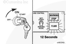
Alerting the Operator The maintenance monitor will alert the operator of the need to change the oil by flashing the MAINTENANCE (FLUID) lamp with five sets of three quick flashes after the keyswitch is in the ON position. The flashing sequence will go through five cycles in a 12-second period. The sequence will occur at every key-on until the maintenance monitor has been reset. NOTE: The diagnostic switch must be in the OFF position for the flashing sequence to occur.Viewing maintenance monitor data is done through the electronic service tool and the following data can be printed from the ECM:
|
|
 |
|
Reset Log
The maximum threshold is entered by the user either directly by using the manual distance or time mode or by entering the interval factor in the automatic mode. The adjusted threshold is the new threshold set automatically by the maintenance monitor when automatic mode is selected. Maintenance monitor automatically reduces the maintenance interval when the engine is operating outside the optimum oil temperature range. The longer the engine operates outside optimum temperature, the more the adjusted threshold is reduced.
Resetting the Maintenance Monitor
The maintenance monitor can be reset using an electronic service tool or by following steps 1 through 10. Steps 3 through 8 must be done within 12 seconds for the maintenance monitor to be reset. The diagnostic switch
must be in the OFF position and the vehicle air system must be fully charged.
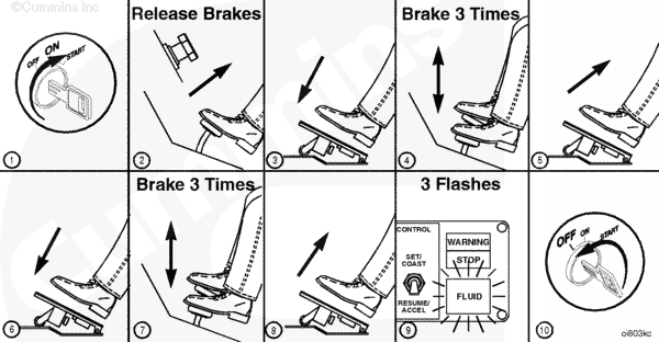 |
- Turn the keyswitch to the ON position (engine must not be operating).
- Make sure brakes are released (service and trailer brakes).
- Hold accelerator pedal at 100-percent accelerator.
- Press and release service brake three times.
- Release accelerator pedal.
- Depress and hold accelerator pedal at 100-percent accelerator again.
- Press and release service brake three more times.
- Release accelerator pedal.
- The lamp will flash three times.
- Turn the keyswitch to the OFF position for at least 30 seconds.
Multilevel Security
The feature provides several modes of security for vehicle performance, operational safety, and protection of individual settings in the ECM. This reduces the risk of unauthorized program changes or clearing of information in the ECM.
Setup Information
Multilevel security consists of four levels of passwords:
- Master password
- Adjustment password
- Reset password
- OEM password.
This flexibility allows for fleet operations to assign access rights set to their own criteria.
- ECM master password locks out the following:
- Feature selection and parameter adjustments
- Calibration transfers to the ECM
- Reset engine protection data
- Reset trip information
- Resetting the maintenance monitor
- Changing adjustment and reset passwords.
- Adjustment password locks out the following:
- Feature selection and parameter adjustments
- Calibration transfers to the ECM.
- Reset password locks out the following:
- Reset engine protection data
- Reset trip information
- Resetting the maintenance monitor.
- OEM password locks out the following:
- OEM powertrain protection.
Power Take-Off (PTO)
The PTO feature controls the engine at a constant rpm selected by the driver/operator. PTO can be used on the following applications:
- Mixers
- Dry bulk haulers
- Dump trucks
- Refuse vehicles
- Other.
Engine speed for PTO can be set either in cab or remotely, through control switches, where a remote-mounted switch can be used where a cab switch is not desirable. Also, the cruise control switches are used for the PTO feature.
Setup Information
The parameters for the PTO feature are described below.
PTO Minimum Engine Speed
This feature is the lowest engine speed setting at which the PTO will operate. It can be set as low as the engine low-idle speed. PTO set switch engine speed, PTO resume switch engine speed, and PTO additional switch engine speeds
must be set equal to or greater than the PTO minimum engine speed.
PTO Maximum Engine Speed
This feature is the highest engine speed setting at which the PTO will operate. PTO set switch engine speed, PTO resume switch engine speed, and PTO additional switch engine speeds must be set equal to or less than the PTO maximum engine speed.
PTO Ramp Rate
This feature defines the rate of engine speed change (rpm per second) in PTO mode when the operator is accelerating up or coasting down. The PTO speed is adjusted by either bumping or holding the increment/decrement PTO set/resume switch.
PTO Accelerator Override
The feature allows the driver/operator to increase engine speed temporarily beyond the PTO reference speed during PTO operation using the accelerator pedal.
PTO Accelerator Override Maximum Engine Speed
This feature is the maximum engine speed the accelerator can override the PTO reference speed. This parameter must be set equal to or greater than PTO maximum engine speed.
PTO Maximum Vehicle Speed
This parameter is the maximum allowed vehicle speed during PTO operation.
PTO Set/Resume Engine Speed
This feature is the engine rpm that the engine will hold when the PTO set-resume switch is used.
Clutch Override
PTO, when enabled, will allow the PTO to deactivate when the clutch pedal is depressed.
Brake Override
PTO, when enabled, will allow the PTO to deactivate when the service brake pedal is depressed.
|
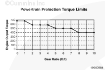
Powertrain Protection The powertrain protection feature provides torque management capabilities that prevent the engine from exceeding the rated torque capacity of drivetrain components. Tailoring the maximum engine torque output to meet the torque rating of the drivetrain components prevents damage to these components due to excessive torque and allows the utilization of lower cost drivetrain components. Refer to the OEM service manual for transmission, driveshaft, and axle torque limits. |

|
 |
|
Setup Information
This feature offers three categories of protection: Switched, Driveshaft/axle, and Transmission.
- Switched Protection: This feature reduces excessive torque whenever a switched torque limit is desired. It requires an OEM-supplied torque limit switch, which is usually mounted on the transmission shifter.
- Driveshaft/Axle Protection: This feature reduces excessive torque for drivetrain components located after the main transmission.
- Transmission Protection: The feature reduces excessive torque applied to the main transmission.
Detailed Operation and Interaction Information
Powertrain Protection
Powertrain lugback is similar to an electronic smart power rating, in that it provides both fuel economy and power. This feature imposes a lower torque limit when the engine load is low, thereby improving fuel economy; and imposes a higher torque limit when the engine is “lugging back,” thereby providing more power. Lugback is in effect when the engine is at or near maximum fueling, yet the vehicle is decelerating. While operating in the top gear range and not lugging back, the engine torque limit requested will be that of the intermediate gear range. However, if lugback is in effect while operating in the top gear range, the engine torque limit requested will be that of the top gear range.
NOTE:
- Do not enable powertrain protection on an electronic smart power engine.
- The maximum torque allowed for the intermediate gear range must be programmed lower than the maximum torque allowed for the top gear range.
- If the customer complains of low power check to see if the feature is enabled incorrectly or any parameters are trimmed incorrectly.
Maximum Torque Allowed Switched and Switched Torque Limit
If switched protection is desired and a torque limit switch is installed, then obtain torque ratings for all drivetrain components downstream of the transmission, typically driveshafts and axles. Backward-calculate the engine torque that will apply the rated torque for all drivetrain components. The calculation is as follows: (torque rating)/(highest gear ratio). Set this parameter at the lowest calculated engine torque of any component.
Driveshaft/Axle Torque Limit
This value can be programmed at the lowest rating of any drivetrain component downstream of the main transmission, such as driveshafts, axles, and intermediate auxiliary transmissions. Because powertrain protection compensates for the transmission gears, no calculation is necessary.
Maximum Torque at Zero Road Speed
This value is the driveshaft/axle torque limit divided by the gear ratio of the lowest gear (highest gear ratio) on the main transmission.
The following tables are examples of engine torque capacities: Example 1 consists of a high-output engine coupled to a six-gear transmission with a single torque capacity rating. Driveshaft and axle are underrated for economy. Powertrain lugback has been enabled according to customer request.
| Engine | Transmission | Driveshaft | Axle |
| 430 ft-lb | Gears 1 to 6: 400 ft-lb | 3500 ft-lb | 3000 ft-lb |
| Gear 1 ratio: 8.0:1 | N/A | N/A | |
| Gear 6 ratio: 1.0:1 | N/A | N/A |
| Parameter | Setting | Rationale |
| Powertrain lugback enable | Enable | Desired by end user |
| Switched torque limit | 2500 ft-lb | Not used; leave at default value |
| Driveshaft/axle torque limit | 3000 ft-lb | Axle has lower torque capacity |
| Maximum torque at zero road speed | 375 ft-lb | 3000/8.0 = 375 ft-lb |
| Maximum torque allowed by transmission top gear range | 400 ft-lb | Gears 5 to 6 lugback torque |
| Maximum torque allowed by transmission intermediate gear range | 380 ft-lb | Gears 5 to 6 nonlugback torque. Gears 1 to 6 reduced torque (customer request due to lugback feature) |
| Maximum torque allowed by transmission bottom gear range | 380 ft-lb | Gears 1 to 6 reduced torque |
| Gear ratio of lowest gear of transmission top gear range | 1.0 | Gear 6 ratio |
| Gear ratio of lowest gear of transmission intermediate gear range | 1.0 | Not used; leave at default value |
Example 2 consists of a high-output engine coupled to a 6 gear transmission with a dual torque capacity rating. Driveshaft and axle are underrated for economy. A transfer case between the transmission and axle provides deep reduction when the torque limit switch is active.
| Engine | Transmission | Auxiliary Transmission | Axle |
| 430 ft-lb | Gears 1 to 5: 400 ft-lb | 2800 ft-lb | 3000 ft-lb |
| Gears 5 to 6: 430 ft-lb | Gear ratio: 1:1 or | N/A | |
| Gear 1 ratio: 8.0:1 | Gear ratio: 2.04:1 | N/A | |
| Gear 6 ratio: 1.0:1 | N/A | N/A |
| Parameter | Setting | Rationale |
| Powertrain lugback enable | Disable | Not desired by end user |
| Switched torque limit | 184 ft-lb | 3000/(8.0 x 2.04) |
| Driveshaft/axle torque limit | 2800 ft-lb | Auxiliary transmission has lower torque capacity than driveshaft or axle. |
| Maximum torque at zero road speed | 350 ft-lb | 2800/8.0 |
| Maximum torque allowed by transmission top gear range | 430 ft-lb | Gear 6 torque capacity |
| Maximum torque allowed by transmission intermediate gear range | 400 ft-lb | Gears 1 to 5 torque capacity |
| Maximum torque allowed by transmission bottom gear range | 400 ft-lb | Gears 1 to 6 capacity |
| Gear ratio of lowest gear of transmission top gear range | 1.0 | Gear 6 ratio |
| Gear ratio of lowest gear of transmission intermediate gear range | 1.0 | Not used; leave as default value |
Remote Accelerator
The remote accelerator feature allows an operator to control engine speed external to the cab accelerator. This is helpful when operating PTO devices.
Setup Information
When the remote accelerator is active, the remote accelerator device controls the selected governor, variable speed (VS), or automotive. Refer to the automotive or VS governor section. The selected governor commands engine fueling while the cab accelerator input is ignored.
The remote accelerator feature and all functions are activated by enabling the feature using the electronic service tool. When this feature is disabled or not being used, the remote accelerator on/off switch does not affect the cab accelerator operation.
Detailed Operation and Interaction Information
The operator activates the remote accelerator feature by placing the remote accelerator on/off switch in the ON position. Once the driver/operator places the switch in the ON position, the following conditions must be met in order for the remote accelerator to function:
- The remote accelerator device must be set initially to command less fueling than the cab accelerator. This is done to prevent sudden acceleration when switching over to remote accelerator control.
- A remote accelerator fault code condition is not present.
To turn off the remote accelerator and return to the cab accelerator control, the cab accelerator must be set to command less fueling than the remote accelerator device to prevent sudden engine acceleration. The remote accelerator switch must then be turned to the OFF position.
Remote Power Take-Off (PTO)
Remote PTO is used on the following applications:
- Mixers
- Dry bulk haulers
- Dump trucks
- Refuse vehicles
- Other.
Remote PTO allows the PTO mode to be activated from a separate remote switch that controls the engine at a constant engine rpm. Remote PTO has up to five driver/operator selectable speed settings that are independent of the normal PTO speed settings. When activated, remote PTO will override the normal PTO speed settings. Remote PTO speed settings can be activated by toggling the remote PTO switch.
Setup Information
This feature is enabled in the ECM using the electronic service tool. The range of the remote PTO speed setting is limited by the normal PTO minimum and maximum speeds. The accelerator can be used to increase engine speed if the normal PTO accelerator override feature is turned on in the ECM. The engine speed can only be increased up to the PTO accelerator override maximum speed. The maximum torque output for all selectable remote PTO set speeds is defined by the normal PTO maximum engine load. This parameter limits highest allowable torque output of the engine when in remote PTO mode; thus the weakest PTO-driven device is protected from being damaged by excessive engine output torque. The normal PTO maximum vehicle speed setting is in effect when using remote PTO. This setting will limit the maximum vehicle speed that is attainable when using the remote PTO feature. The normal PTO droop setting is in effect when using remote PTO. This setting will slow the engine slightly below the selected speed setting under heavy engine loads. All remote PTO speed settings can not be adjusted above the maximum PTO speed or below the minimum PTO speed. The remote PTO feature can not be activated if a vehicle speed sensor (VSS) fault code is active. Remote PTO can only be deactivated by moving the remote PTO on/off switch to the OFF position.
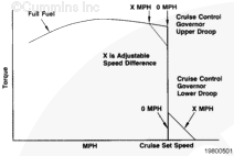
Road Speed Governor
This feature controls the vehicle’s maximum road speed. The customer can program the maximum vehicle speed in top gear. In order for the electronic control module (ECM) to calculate the road speed correctly, the customer must enter the vehicle speed sensor type, vehicle’s tire size, rear axle ratio(s), and number of tailshaft gear teeth. The customer can also adjust the upper and lower droop settings.
NOTE: In some worldwide territories road speed governing is subject to local laws legislation that dictates road speed governor lower droop must be disabled. For these territories road speed governor lower droop is disabled within the engine calibration and can not be enabled with electronic service tool.
Setup Information
| Parameter Name | Range and Settings |
| Maximum vehicle speed in top gear | XXX mph |
| Road speed governor upper droop | X mph |
| Road speed governor lower droop | X mph |
NOTE: Due to local regulations limiting maximum road speed this feature will possibily not be available in some areas of the world.
Detailed Operation and Interaction Information
Maximum vehicle speed in top gear
This parameter is the maximum road speed for the vehicle. This speed must be as high as the maximum vehicle speeds used for gear-down protection (if gear-down protection is enabled) and cruise control.
Road speed governor upper droop
This parameter is the amount of vehicle speed decrease before full torque is reached while operating on the road speed governor. Increasing this rate can improve fuel economy in hilly terrain.
Road speed governor lower droop
This parameter is the amount of vehicle speed increase in a downhill or no-load condition while operating on the road speed governor before fuel is completely cut off. An increased downhill speed can increase momentum up the next hill and improve fuel economy.
NOTE: Due to local regulations limiting maximum road speed this feature will possibily not be available in some areas of the world.
|
Accelerator Manual Vehicle Switch The smart road speed governor feature, when enabled, allows the driver/operator to adjust the maximum vehicle speed by using an OEM switch, typically the cruise control accel/resume switch. This feature can be used for city driving when reducing maximum vehicle speed can help prevent speeding tickets. To adjust the maximum vehicle speed limit, the cruise control on/off switch must be off and the coast/accel switch can be used to raise or lower the preset limit. NOTE: The maximum speed limit can not be adjusted above the predefined maximum vehicle speed in top gear limit.Set Engine Speed This feature allows the electronic service tool to override the accelerator pedal and control the engine speed to a value set within the electronic service tool. The set value is limited to the normal operating engine speed (rpm) range of the engine. |
 |
||
Starter Lockout
The starter lockout feature will prevent the starter motor from engaging when the engine is already started and running. This is intended to increase starter motor life.
Setup Information
Starter lockout can be activated by enabling the feature using the electronic service tool.
Detailed Operation and Interaction Information
Starter motor engagement is allowed whenever the engine state is such that the starter will be needed. These states are shutdown, stop, crank, and jump start. Starter motor engagement is not allowed whenever the engine state is such that the starter is not needed. These states are run, brake, and overspeed. This feature is not compatible with the ICON™ feature. If ICON™ is installed and turned on, then starter lockout can not be enabled or activated.
Vehicle Antitheft Protection
The antitheft feature can only be used with vehicles equipped with Cummins Road Relay™ and is used to secure the engine in the idling or shutdown state. The antitheft feature is enabled by either the Cummins INSITE™
service tool or Cummins INSPEC™ fleet management tool.
When activated, the antitheft feature requires one of the six preprogrammed passwords to be entered using the Road Relay™ keypad before the engine can be started. When activated at idle, the antitheft feature will lock the accelerator pedal at idle and only allow normal accelerator operation when a valid password is entered. If an unauthorized attempt is made to start the engine with the antitheft feature active, a fault code will be logged and a red lamp will flash.
If an incorrect password is entered when deactivated antitheft, the operator will be prompted to re-enter the correct password. If the correct password is entered, the operator will be prompted to enter it again to confirm the password. If the correct password is not entered in five attempts, antitheft will lock out any further attempts for 10 minutes. After 10 minutes have elasped, antitheft will lock out any further attempts for 10 minutes. After 10 minutes have elasped, antitheft can then be deactivated with the correct password.
Setup Information
The antitheft feature will prevent the engine from starting only if the feature is enabled and activated. The feature can only be activated when the engine is idling or keyed on and not
running. This feature has three separate functionalities:
- Antilock feature
- Throttle locking
Antilock Feature
There are two user-selectable modes of operation:
- Automatic
- Manual.
In automatic mode, the engine is always locked by the ECM at each engine shutdown. No password is required to activate antitheft. A password is required to deactivate antitheft. The feature will not lock automatically if the engine stopped because of an unintended stall.
In manual mode, activation requires operator action to lock the engine. The user is prompted to activate the security by answering a YES/NO question. If the user answers YES, the user must then key on the engine. If a PIN is required (user-selectable option), the user is prompted to enter the correct PIN to activate antitheft. If no PIN is required, then the antitheft is activated.
There are six user passwords capable of locking or unlocking the engine. These are stored in the ECM and adjusted by an electronic service tool.
A fault will be logged and a red dash lamp will flash if the antitheft feature is active and an attempt to start the engine is made.
Vehicle Setup (adjustable parameters)
Vehicle setup is a group of programmable parameters used to configure the ECM to the vehicle in which it is being used. This group of parameters only requires adjustment when the vehicle is first put into service or when a change is made to the vehicle after it has been in service.
Vehicle Speed Sensor (VSS) Type – This parameter informs the ECM which type of vehicle speed sensor is installed on the vehicle. This parameter can be programmed using an electronic service tool. The ECM can convert vehicle speed information from the following signal sources: Magnetic VSS, mechanical VSS, tachograph, datalink VSS, or datalink tailshaft. The operator can select other or none.
-
Magnetic VSS – This VSS type is used in conjunction with a speedometer gear, also called a tone wheel, mounted on the transmission tailshaft. The number of teeth on the speedometer gear must
be defined by the number of transmission tailshaft gear teeth parameter. The magnetic VSS generates pulses as the speedometer gear teeth rotate past the sensor. - Mechanical VSS – This VSS, also called a minigen, is driven by the transmission’s speedometer cable. The cable rotates a magnet through a coil to induce current flow. It is similar to a generator.
- Tachograph – This device is a dash-mounted speedometer used primarily for Europeon applications. The device supplies a digital stream of data containing vehicle speed information.
- Datalink VSS – A proprietary J1939 message containing vehicle speed is transmitted to the ECM over the J1939 datalink. It is also known as J1939 with gear ratio.
- Datalink Tailshaft – A standard SAE J1939 message supplied by a transmission equipped with its own VSS. The message consists of transmission tailshaft speed in rpm.
- Other – A sensor that provides a signal to the ECM in pulses per mile. When selected, the pulses per mile must be defined by the vehicle speed sensor (VSS) pulses parameter.
- None – No vehicle speed sensor (VSS) present on vehicle.
Rear Axle Ratio – This parameter defines the rear axle ratio for use in vehicle speed calculations. This parameter can be programmed using an electronic service tool. The ECM uses this parameter, tire revolutions per mile, and number of transmission tailshaft gear teeth to determine vehicle speed. This parameter applies when VSS type is magnetic.
Two-Speed Rear Axle – Two-speed axles have capability of switching from one rear axle ratio to another. Selecting this feature allows the ECM to calculate vehicle speed correctly.
Tire Revolutions per Mile – This parameter is the vehicle’s tire size for use in vehicle speed calculations. This parameter can be programmed using an electronic service tool. The ECM uses this parameter, rear axle ratio, and number of transmission tailshaft gear teeth to determine vehicle speed. This parameter applies when VSS type is magnetic.
Number of Transmission Tailshaft Gear Teeth – This parameter is the number of teeth on the speedometer gear that is used in conjunction with an electrical vehicle speed sensor. This parameter can be programmed using an electronic service tool. The ECM uses this parameter, rear axle ratio, and tire revolutions per mile to determine vehicle speed. This parameter applies when VSS type is magnetic.
Top Gear Transmission Ratio – This parameter is the number of engine revolutions divided by the number of transmission tailshaft revolutions when the transmission is in top gear. This parameter can be programmed using an electronic service tool. This parameter is used by gear-down protection, Top 2™ autoshift.
Gear-Down Transmission Ratio – This parameter is the number of engine revolutions divided by the number of transmission tailshaft revolutions when the transmission is in first gear-down. This parameter can be programmed using an electronic service tool. This parameter is used by gear-down protection, Top 2™ autoshift, and VSS antitampering.
Transmission Type – This parameter provides transmission type – manual or automatic. This parameter can be programmed using an electronic service tool. This parameter is used by compromised vehicle speed. Select transmission type as follows:
- Manual – This transmission is shifted by the driver through every gear.
- Automatic – This transmission performs automatic shifts in every gear. It contains a torque converter.
- Fully automated – This transmission performs automated shifts, sending engine torque commands to the engine ECM during shifts. It typically does not contain a torque converter.
- Partially automated – This transmission performs automatic shifts in upper gears and is manually shifted in lower gears. Eaton Top 2™ is an example of a partially automated transmission.
Detailed Operation and Interaction Information
The speed sensor type tells the ECM what type of VSS is used in the vehicle. If mechanical is selected, then pulses per mile in the ECM will automatically be set to 48,280 pulses/km [30,000 pulses/mi].
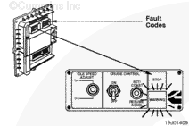
Diagnostic Fault Codes |
||||||||||||||||||||||||||||||||||||
|
||||||||||||||||||||||||||||||||||||
;)
;)
;)
;)
;)
;)
;)
;)
;)
;)
;)
;)
;)
;)
;)
;)
;)
;)
;)
;)
;)
;)
;)
;)
;)
;)
;)
;)
;)
;)
;)
;)
;)
;)
;)
;)
;)
;)
;)
;)
;)
;)
;)
;)
;)
;)
;)
;)