ISBe/ISB Series Engines – 005-016   Fuel Pump

General Information

TOC

 WARNING 

The fuel pump, high-pressure fuel lines, and fuel rail contain very high-pressure fuel. Do not loosen any fittings while the engine is running. Wait at least 10 minutes after shutting down the engine before loosening any fittings in the high-pressure fuel system to allow pressure to decrease to a lower level.
 CAUTION 

Use caution when disconnecting or removing fuel lines, replacing filters and priming the fuel system, so that fuel is not spilled or drained into the bilge area. Do not drop or throw filter elements into the bilge area. The fuel and fuel filters must be discarded in accordance with local environmental regulations.
 CAUTION 

Be sure that the fuel inlet and return valves are returned to the open position before cranking the engine. Engine damage can result if the valves are in the wrong position when the engine is cranked or started. Environmental damage can also occur.

There are four different mounting locations available for high-pressure fuel pumps. The pump can be mounted in a high or low position in either a front or rear gear train engine. Due to the number of different fuel pump mounting locations, the steps in this procedure have been written to be generic. Some of the illustrations do not represent the parts being removed or installed.

Refer to Procedure 005-999 in Section F.

SMALL | MEDIUM | LARGE

Test

TOC

 CAUTION 

Clean all fittings before disassembly. Dirt or contaminants can damage the fuel system.

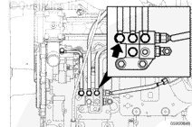
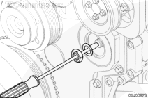
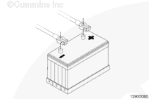
If the engine will not start, disconnect the high-pressure fuel outlet line from the high pressure injection pump.  Refer to Procedure 006-060 in Section 6. 

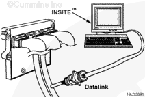
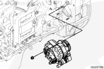
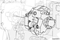
Disconnect the fuel pump actuator connector. 

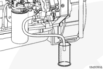
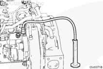
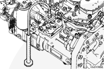
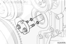
Insert a clear hose to the outlet of the high pressure injection pump, and run the other end into an empty bucket. 

Crank the engine and measure the amount of fuel exiting the fuel pump.

NOTE: Do not crank the engine for 30 seconds continuously.  Crank the engine in 10 second intervals with a 30 second break between cranking.  This reduces the possibility of overheating the starter motor.

 
Fluid Measure
Time
Engine Speed
4-cylinder
75 ml [2.5 oz]
30 seconds
125 rpm
6-cylinder
90 ml [3.04 oz]
30 seconds
150 rpm

If the high pressure injection pump does not meet the flow specifications:

Check for air in the fuel. Refer to Procedure 006-003 in Section 6.

Check for inlet restriction. Refer to Procedure 006-020 in Section 6.

Check the fuel filter restriction. Refer to Procedure 006-015 in Section 6.

If these checks are acceptable, replace the fuel pump actuator. Refer to Procedure 005-007 in Section 5.

After replacing the fuel pump actuator, measure the fuel pump flow again.  If the flow is not within specification, replace the fuel pump.

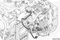
Connect the high pressure fuel line and the fuel pump actuator electrical connection.

SMALL | MEDIUM | LARGE


 WARNING 

The fuel pump high-pressure fuel lines and fuel rail contain very high-pressure fuel. Never loosen any fittings while the engine is running. Personal injury and property damage can result.

If the engine can be started, a measurement of the fuel return flow can diagnose a high-pressure fuel pump problem. The following steps describe how to test the high-pressure fuel pump return flow.

A malfunctioning fuel return overflow valve or fuel pump can result in high return from the fuel pump.

The return fuel flow from the pump must be measured at idle conditions. The fuel system leakage test in the INSITE™ electronic service tool can be used to increase system pressure and therefore increase the ability to detect high leakage.

 
SMALL | MEDIUM | LARGE
   

Without Electric Lift Pump


Disconnect the fuel pump return line.

3.9L and 5.9L Engines

  • Attach the fuel pressure gauge adapter, Part Number 3164044, to the fuel pump return fitting. Install a quick-disconnect block-off fitting, Part Number 3164583, on the disconnected drain line.

4.5L and 6.7L Engines

  • Attach the female quick-disconnect fuel drain hose, Part Number 4918434, onto the fuel pump drain connection. Install a quick-disconnect block-off fitting, Part Number 4918464, on the disconnected drain line.

SMALL | MEDIUM | LARGE
   

With Electric Lift Pump


 CAUTION 

If tool Part Number 3164618 is installed at the fuel pump, it will block return flow and cause possible damage to the fuel pump. Install tool Part Number 3164618 only at the fuel return manifold.

Follow the fuel return line from the fuel pump to the fuel return manifold. At the fuel return manifold, remove the banjo bolt for fuel pump return line and install test fitting, Part Number 3164618.

For automotive and industrial applications, the return manifold is located near the top of the engine, beside the fuel rail.

SMALL | MEDIUM | LARGE


For marine engines, the return manifold is located on the side of the engine block, next to the ECM.

SMALL | MEDIUM | LARGE


 WARNING 

Fuel can be returned at highly elevated temperatures. Wear safety glasses and protective gloves and clothing when performing this test. Avoid contact with returned fuel.

Place the end of the fuel pressure gauge adapter tool or fuel drain hose into a 500 ml graduated beaker, Part Number 3823705.

Start the engine.

Measure the flow rate by recording the amount of time required to fill the beaker to the 400 ml lever. Flow Specification: Standard Idle Conditions (750 rpm) 4- and 6-cylinder 400 ml (maximum) in 25 seconds

Maximum Flow: Standard Idle Conditions (750 rpm)
4- and 6-cylinder
400 ml in 25 seconds

SMALL | MEDIUM | LARGE
   

Remove

TOC

NOTE: A counter-torque must be applied to the fitting on the high-pressure pump. This is to prevent the fitting from being loosened and to prevent the possibility of a leak.

Disconnect the high-pressure supply line from high-pressure fuel pump to the fuel rail and loosen the holding brackets.

Disconnect the EFC actuator valve wire harness connector.

SMALL | MEDIUM | LARGE
   

Rear Gear Train


Remove the three flanged fuel pump mounting nuts.

Remove the fuel pump from the gear housing.

SMALL | MEDIUM | LARGE
   

Front Gear Train


Remove the fuel pump drive access cover with a 3/8-inch drive ratchet.

SMALL | MEDIUM | LARGE


 CAUTION 

Place a clean cloth in the air-gap between the fuel pump drive gear and the gear cover, or use a screwdriver to prevent the mounting nut and lock washer from being dropped into the front gear train.
 CAUTION 

The fuel pump drive gear is captive between the gear housing and the gear cover. Do not rotate the engine while the gear is not supported by the fuel pump drive shaft. The gear, gear housing or gear cover can be damaged.

Remove the fuel pump drive gear retaining nut and lock washer.

SMALL | MEDIUM | LARGE


 CAUTION 

Protect the fuel pump drive shaft threads from damage during gear removal.

Install the fuel pump drive gear puller onto the drive shaft and gear.

Hold the gear puller while removing the fuel pump drive gear.

SMALL | MEDIUM | LARGE


Remove the fuel pump assembly.

SMALL | MEDIUM | LARGE
   

Install

TOC

Automotive and Industrial


Install the fuel pump on the gear housing.

NOTE: Timing of the high-pressure pump with the crankshaft is not required.

SMALL | MEDIUM | LARGE


Install the fuel pump mounting nuts and tighten.

Torque Value:  25  n.m  [221 in-lb]

SMALL | MEDIUM | LARGE


Install the high-pressure supply line from the high-pressure pump to the fuel rail and tighten the holding brackets.

NOTE: Apply a counter-torque on the high-pressure pump outlet port to prevent over-tightening.

Torque Value:

3.9L and 5.9L High Pressure Supply Line

  1. 30 n.m   
    [22 ft-lb]
Torque Value:

4.5L and 6.7L High Pressure Supply Line

  1. 30 n.m   
    [22 ft-lb]

Connect the EFC actuator valve wire harness connector.

SMALL | MEDIUM | LARGE
   

Front Gear Train


 CAUTION 

Place a clean cloth in the air-gap between the fuel pump drive gear and the gear cover, or use a screw driver to prevent the mounting nut and lock washer from being dropped into the front gear train.
 CAUTION 

The fuel pump drive gear is captive between the gear housing and the gear cover. Do not rotate the engine while the gear is not supported by the fuel pump drive shaft. The gear, gear housing or gear cover can be damaged.

NOTE: The engine barring tool, Part Number 3824591, can be used to prevent the crankshaft from rotating while tightening the retaining nut.

Install the drive gear retaining nut and lock washer onto the drive shaft. Tighten the gear retaining nut.

Torque Value:  105  n.m  [77 ft-lb]

SMALL | MEDIUM | LARGE


Install a new square cut o-ring onto the fuel pump drive access cover.

Install the fuel pump drive access cover with a 3/8-inch drive ratchet. The plate is threaded into the gear cover.

Torque Value:  8  n.m  [71 in-lb]

SMALL | MEDIUM | LARGE
   

Finishing Steps

TOC

With Electric Lift Pump


SMALL | MEDIUM | LARGE


 WARNING 

Batteries can emit explosive gases. To reduce the possibility of personal injury, always ventilate the compartment before servicing the batteries. To reduce the possibility of arcing, remove the negative (-) battery cable first and attach the negative (-) battery cable last.
  • Connect the batteries. Refer to the OEM service manual.
  • Prime the fuel system. See the Prime section in this procedure.

SMALL | MEDIUM | LARGE
   

Prime

TOC

Automotive and Industrial


 WARNING 

The fuel pump high-pressure fuel lines and fuel rail contain very high-pressure fuel. Never loosen any fittings while the engine is running. Personal injury and property damage can result.
 CAUTION 

Be sure that the fuel inlet and return valves are returned to the open position before cranking the engine. Engine damage can result if the valves are in the wrong position when the engine is cranked or started. Environmental damage can also occur.
 CAUTION 

Use caution when disconnecting or removing fuel lines, replacing filters and priming the fuel system, so that fuel is not spilled or drained. The fuel and fuel filters must be discarded in accordance with local environmental regulations.

Refer to Procedure 005-999 in the Familiarization section for further information.

 
SMALL | MEDIUM | LARGE
   

With Electric Lift Pump


Allow the lift pump to run by turning the key switch ON and waiting 30 seconds before starting.

NOTE: It is not necessary to vent air from the high-pressure fuel system before starting the engine. Cranking the engine will prime the fuel system.

Operate the engine and check for leaks.

 
SMALL | MEDIUM | LARGE
   

With Hand Priming Pump


Dry Fuel Filter and Fuel Tubes: this condition occurs if the engine has come from the manufacturing plant without being tested before shipping, if the fuel filters have been changed. Before starting the engine, pump the hand priming pump 120 times.

Full Fuel Filter and Fuel Tubes: This condition occurs if the engine is being installed for the first time after being built, but was tested at the manufacturing plant or is being installed again. Before starting the engine, pump the hand priming pump 40 times.

NOTE:  It is not necessary to vent air from the high-pressure fuel system before starting the engine. Cranking the engine will prime the fuel system.

Operate the engine and check for leaks.

SMALL | MEDIUM | LARGE
Last Modified:  23-Apr-2010