The ISB CM850 engine control system is an electronically operated fuel control system that also provides many operator and vehicle features.
The base functions of the control system include fueling and timing control, limiting the engine speed operating range between the low- and high-idle set points, and reducing exhaust emissions while optimizing engine performance. The system also controls the exhaust brakes.
The control system uses inputs from the operator and its sensors to determine the fueling and timing required to operate at the desired engine speed and at the required emissions level.
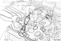
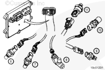
The electronic control module (ECM) is the control center of the system. It processes all of the inputs and sends commands to the fuel system and vehicle and engine control devices.
The ECM performs diagnostic tests on most of its circuits and will activate a fault code if a problem is detected in one of these circuits. Along with the fault code identifying the problem, a snapshot of engine operating parameters at the time of fault activation is also stored in memory.
Active fault codes will cause a diagnostic lamp to activate to signal the driver.
The ECM can communicate with service tools and some other vehicle controllers (such as transmissions, ABS, ASR, electronic dash displays, and so forth) through the SAE J1939 data link or the SAE J1708 data link.
Some vehicles and equipment will have SAE J1939 networks on them that link many of the “smart” controllers together. Vehicle control devices can temporarily command engine speed or torque to perform one of their functions (that is, transmission shifting, anti-lock braking, and so forth).
The electronic engine control system can display and record certain detectable fault conditions. These failures are displayed as fault codes, which make troubleshooting easier. The fault codes are retained in the ECM.
There are two types of diagnostic codes:
Engine electronic control system fault codes are to inform the operator that there is a problem with the control system that will require troubleshooting.
Information and engine protection fault codes are to inform the operator that the control system has detected an engine condition outside the normal operating range.
All fault codes recorded will either be active (fault code is currently active on the engine) or inactive (fault code was active at some time, but is notcurrently active).
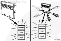
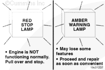
The “Stop” light is red and indicates the need to stop the engine as soon as it can be safely done. The engine mustremain shut down until the fault can be repaired.
The “Warning” light is amber and indicates the need to repair the fault at the first available opportunity.
Maintenance-type fault codes, such as water-in-fuel and maintenance monitor oil change interval, will flash the amber Warning light for 30 seconds after the keyswitch is turned to the ON position.
NOTE: The names and colors of these lamps can vary with equipment manufacturers.
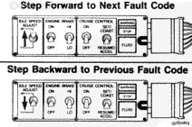
Fault codes can be accessed in at least two different ways: Using the electronic service tool or fault code flashout.
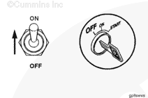
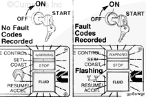
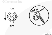
To check for active engine electronic fuel system and engine protection system fault codes, turn the keyswitch to the OFF position and move the diagnostic switch to the ON position.
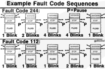
The lights flash each fault code out twice before advancing to the next code. To skip to the next fault code, move the Increment/Decrement switch (if equipped) momentarily to the increment (+) position. You can go back to the previous fault code by momentarily moving the Increment/Decrement switch (if equipped) to the decrement (-) position. If onlyone active fault is recorded, the same fault code will continuously be displayed when either increment (+) or decrement (-) is depressed.
The explanation and correction of the fault codes are covered in Section TF of this manual.
When the ECM receives the signal from the diagnostic on/off switch, the yellow and red warning lights will come on and start flashing if any active fault code is recorded in the ECM. If both warning lights remain on and do notflash, there are no active fault codes present.
NOTE: The equipment mustbe stationary. If road speed is detected, the flashing sequence will notoccur.
The throttle-activated diagnostic switch feature is intended to eliminate the need for a dash-mounted diagnostic switch, which is used to activate the fault code flashout on the lamps. The fault code flashout will be activated through a simple sequence of throttle movements. When this feature is enabled, the engine is in stop state and the keyswitch is turned on. Every successive cycle of the throttle will lead to the next fault code to be flashed on the lamps, in the same manner as if the increment switch were depressed.
To activate this feature, the engine mustbe stopped and the keyswitch turned to the ON position. Then depress the accelerator pedal completely three times. The feature should then be enabled. Transitioning to the next fault code will happen automatically after the first fault code is flashed out twice or if the throttle pedal is cycled.
NOTE: There is an optional, error-sensitive mode for this feature. If any of the throttle-related errors occur, this feature will turn on the diagnostic switch automatically when the engine is stopped and the keyswitch is on. During this mode, onlythe increment switch can be used to flash out the next fault code.
The ISB CM850 engines are equipped with an engine protection system. The system monitors critical engine temperatures and pressures and will log diagnostic faults when an over or under normal condition occurs. If an out-of-range condition exists and engine derate action is to be initiated, the operator will be alerted by an in-cab Warning lamp. The Stop lamp will blink or flash when out-of-range conditions continue to worsen. The driver mustpull to the side of the road, when it is safe to do so, to reduce the possibility of engine damage.
NOTE: Engine power and speed will gradually be reduced, depending on the level of severity of the observed condition. The engine protection system will notshut down the engine unless the engine protection shutdown feature has been enabled.
CAUTION
When the red STOP lamp is illuminated, the driver/operator must pull to the side of the road, when it is safe to do so, to reduce the possibility of engine damage.
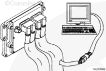
When a diagnostic fault code is recorded in the ECM, the ECM input and output data is recorded from all sensors and switches. Snapshot data allows the relationships between ECM inputs and outputs to be viewed and used during the troubleshooting.
Fault code snapshot data can onlybe viewed using INSITE™.
Hello, I'm Jack, a diesel engine fan and a blogger. I write about how to fix and improve diesel engines, from cars to trucks to generators. I also review the newest models and innovations in the diesel market. If you are interested in learning more about diesel engines, check out my blog and leave your feedback.
View all posts by Jack

 CAUTION
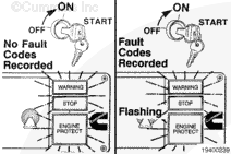
;)
;)
;)
;)
;)
;)
;)
;)
;)
;)
;)
;)
;)
;)
;)
;)
;)
;)
;)
;)
;)
;)
;)
;)
;)
;)
;)
;)
;)
;)
;)
;)
;)
;)
;)
;)
;)
;)
;)
;)
;)
;)
;)
;)
;)
;)
;)
;)
;)
;)
;)
;)
;)
;)