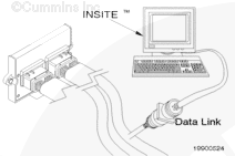
Connect an electronic service tool to the vehicle data link.
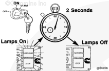
Turn the keyswitch to the ON position.
Select the monitor mode on the electronic service tool. The electronic service tool must be able to communicate with the ECM. If the ECM will not communicate with the service tool, refer to the Communication Error – Electronic Service Tool or Control Device symptom tree in Section TS.
NOTE: Record all of the programmable parameters, features, and calibration information from the old ECM before disconnecting the harness connectors. This information will be needed to program the new ECM.
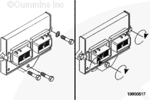
NOTE: In some applications, it can be necessary to disconnect the ignition control module to allow access to the ECM in order to remove it.
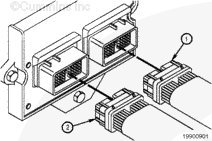
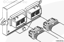
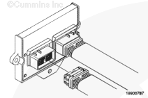
Disconnect engine harness ECM connectors 1 and 2 from the ECM if they are not already removed.
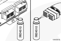
Do not blow compressed air into the ECM ports or connectors. Compressed air can contain moisture due to condensation.
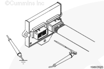
Use quick-dry electrical contact cleaner, Part Number 3824510, to remove all dirt and moisture from the ECM connector ports and the harness connectors.
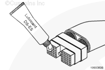
Use only Cummins-recommended lubricant DS-ES, Part Number 3822934. Other lubricants, such as lubricating oil or grease in the connectors, can cause ECM damage, poor engine performance, or premature connector pin wear.
Apply a thin coating of lubricant to the connector nosepiece.
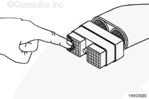
Spread the lubricant across the connector nosepiece so it enters every pin hole and lubricates the contacts. Lubricant must not be visible on the surface of the nosepiece.
Hello, I'm Jack, a diesel engine fan and a blogger. I write about how to fix and improve diesel engines, from cars to trucks to generators. I also review the newest models and innovations in the diesel market. If you are interested in learning more about diesel engines, check out my blog and leave your feedback.
View all posts by Jack


 CAUTION


;)
;)
;)
;)
;)
;)
;)
;)
;)
;)
;)
;)
;)
;)
;)
;)
;)
;)
;)
;)
;)
;)