 CAUTION
Use test lead, Part Number 3822758, for the 50-pin Deutsch connector to reduce the possibility of damage to the connector pins.
|
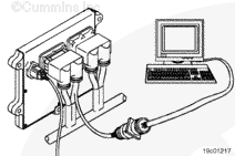
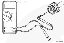
Disconnect the OEM harness connector from the ECM.
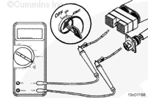
Insert a test lead into the SAE J1587 data link positive (+) pin of the OEM harness connector and connect it to the multimeter probe. Insert the other test lead into the brake pedal position switch signal pin and connect it to the other multimeter probe. Measure the resistance. The multimeter must show an open circuit (100k ohms or more).
If the circuit is not open, repair or replace the OEM harness. Refer to the OEM troubleshooting and repair manual.
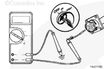
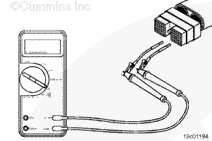
Remove the lead from the brake pedal position switch signal pin and measure the resistance from the SAE J1587 data link positive (+) pin of the OEM harness connector to all other pins in the connector, one at a time. The multimeter must show an open circuit (100k ohms or more).
If the circuit is not open, repair or replace the OEM harness. Refer to the OEM troubleshooting and repair manual.
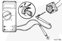
Remove the test lead from the SAE J1587 data link positive (+) pin of the OEM harness connector and insert it into the SAE J1587 data link negative (-) pin. Measure the resistance from the SAE J1587 data link negative (-) pin to all other pins in the connector. The multimeter must show an open circuit (100k ohms or more) at all pins.
If the circuit is not open, repair or replace the OEM harness. Refer to the OEM troubleshooting and repair manual.
Connect all components after repairs are completed.
|


 WARNING
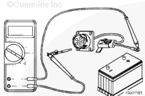

;)
;)
;)
;)
;)
;)
;)
;)
;)
;)
;)
;)
;)
;)