Electronic Control System Gas Plus Engines – 101-007   Electronic Controlled Fuel System

Fuel System Description

TOC

Fuel Flow


This section provides an overview of how fuel and air flow through the engine.

For a detailed description of the individual components, refer to the ECM Inputs and ECM Outputs sections under Electronic Engine Controls.

The engine receives gaseous fuel that is regulated to a certain pressure by the primary regulator. The primary regulator is an OEM-installed component.

 
SMALL | MEDIUM | LARGE


The fuel passes through the primary fuel filter before entering the engine. This filter is to remove any oil that is suspended in the fuel. Oil can cause performance problems if it accumulates in the fuel system.

 
SMALL | MEDIUM | LARGE


The primary fuel pressure sensor allows the ECM to monitor the inlet fuel pressure.

When the filtered fuel enters the engine, the secondary pressure regulator lowers the fuel pressure to a lower value specific for each model.

 
SMALL | MEDIUM | LARGE


The fuel then passes through the fuel shutoff valve. The fuel shutoff valve is a solenoid that is either open or closed.

It then passes a fuel detection point, the secondary fuel pressure sensor, located before the fuel control valve, the secondary fuel pressure sensor. The fuel control valve is also located in the mixer housing.

 
SMALL | MEDIUM | LARGE


Then the fuel proceeds through the gas mass flow sensor. The gas mass flow sensor measures the gas flow through the fuel system.

 
SMALL | MEDIUM | LARGE


The fuel is then mixed with the combustion air in the mixer. The combustion air will have been compressed in the turbocharger compressor and then cooled in the charge air cooler.

After the fuel and air are combined, the mixture passes through the throttle actuator.

After passing through the throttle actuator, the fuel/air mixture enters the intake manifold and then into the cylinders for combustion. The intake manifold air pressure/temperature sensor is located in the intake manifold.

This pressure and temperature information is used to adjust the air to fuel ratio to meet the desired engine performance.

 
SMALL | MEDIUM | LARGE


As the exhaust exits the turbocharger turbine, the heated oxygen sensor measures the amount of oxygen in the exhaust. The ECM can calculate the engine’s actual air/fuel ratio given the amount of oxygen in the exhaust.

 
SMALL | MEDIUM | LARGE
   

Electronic Engine Controls

TOC

Ignition System


The ignition process begins with the electronic control module (ECM) sending ignition information to the ignition control module (ICM).

 
SMALL | MEDIUM | LARGE


Based on the commands from the ECM, the ICM sends firing signals to the individual coils. Each cylinder has its own coil. These firing signals are approximately 300 VDC.

The coils amplify the ICM signals and fire the spark plugs. The signals sent from the coils are approximately 10,000 to 25,000 VDC.

 
SMALL | MEDIUM | LARGE


C Gas Plus and L Gas Plus engines use a coil-on-plug arrangement. Each coil is located directly above the spark plug.

B Gas Plus, B LPG Plus and B Gas International (B Gas International) —engines use ignition coil packs which are located on the intake manifold. A high voltage wire is used to complete the connection to the spark plug.

 
SMALL | MEDIUM | LARGE
   

ECM Inputs


The ECM receives signals from the following sources (not all engines are equipped with all sensors listed):

  • Engine position sensor
  • Throttle position sensor (internal to throttle actuator)
  • Engine coolant temperature sensor
  • Intake manifold air pressure/temperature sensor
  • Mixer inlet pressure sensor
  • Gas mass flow sensor
  • Heated oxygen sensor
  • Diagnostic switch
  • Fuel pressure sensor, primary
  • Fuel pressure sensor, secondary
  • Engine oil pressure/temperature sensor
  • Knock sensors (two)
  • Exhaust back pressure sensor
  • Vehicle speed sensor (VSS)
  • Switched inputs
  • Accelerator pedal
  • Humidity sensor
  • Compressor inlet temperature (L Gas Plus)
  • Air inlet restriction sensor (L Gas Plus).
 
SMALL | MEDIUM | LARGE


The B Gas Plus, B LPG Plus, B Gas International and C Gas Plus engines use an engine position sensor that measures engine speed by counting notches in the cam gear as the gear rotates. The sensor uses a 6 + 1 system where there are 6 evenly spaced notches in the cam gear with an extra notch between two of the evenly spaced notches. This allows the ECM to accurately measure engine speed, while the one extra notch tells the ECM the exact position of the camshaft. This information allows the ECM to control the spark timing.

 
SMALL | MEDIUM | LARGE


The L Gas Plus engine uses an engine speed/position sensor that measures engine speed by counting notches in the camshaft tone wheel as the wheel rotates. The tone wheel has one location with a double wide space that identifies Top Dead Center of the number one cylinder. This allows the ECM to accurately measure engine speed, while the one extra notch tells the ECM the exact position of the camshaft. This information allows the ECM to control the spark timing.

The L Gas Plus engine uses a secondary engine speed/position sensor that measures engine speed by counting notches in the crankshaft tone wheel as the wheel rotates. This allows the ECM to accurately measure engine speed. This information allows the ECM to control the spark timing and overspeed protection.

 
SMALL | MEDIUM | LARGE


The throttle position sensor is internal to the throttle actuator and measures the position of the throttle plate. The ECM controls the throttle position to regulate speed against fueling.

 
SMALL | MEDIUM | LARGE


The intake manifold air pressure/temperature sensor is a combination sensor. The absolute air pressure side determines the pressure of the air/fuel mixture in the intake manifold by measuring the capacitance of two circular plates in the sensor. As the manifold pressure changes, the distance between the plates changes, causing a change in the capacitance of the plates. The sensor has a built-in printed circuit board that converts the capacitance measurement to a signal the ECM can use. The temperature side determines the temperature of the air/fuel mixture in the manifold. This is done by measuring the resistance of the sensor. The ECM receives this signal and measures the voltage drop across a known resistance in the ECM that is in series with the sensor.

NOTE: This is an absolute pressure sensor.

 
SMALL | MEDIUM | LARGE


The engine coolant temperature sensor determines the coolant temperature in the cylinder head. This is done by measuring the resistance of the sensor. The ECM receives this signal and measures the voltage drop across a known resistance in the ECM that is in series with the sensor.

The L Gas Plus engine also uses this sensor to measure coolant pressure and functions as the other combination pressure/temperature sensors on the engine.

 
SMALL | MEDIUM | LARGE


The mixer inlet pressure sensor determines the pressure of the air (boost pressure), before it’s combined with fuel in the mixer. This is accomplished by measuring capacitance of two circular plates in the sensor. As the mixer inlet pressure changes, the distance between the plates changes, causing a change in the capacitance of the plates. The sensor has a built-in printed circuit board that converts the capacitance measurement to a signal the ECM can use.

NOTE: This is an absolute pressure sensor.

 
SMALL | MEDIUM | LARGE


The gas mass flow sensor (GMFS) determines the amount of fuel being mixed with intake air. The sensor is a hot wire anemometer that measures the amount of power required to keep an electrically heated wire at a constant temperature. The wire requires more power to maintain a constant temperature as more fuel flows by the wire. The sensor has a built in printed circuit board that controls the sensor. In order for the gas mass flow sensor to function properly, the fuel must be free of turbulence and have no oil contamination. A screen pack is installed after the fuel shutoff valve to minimize fuel turbulence.

 
SMALL | MEDIUM | LARGE


The heated oxygen sensor (HOS) determines the amount of oxygen in the exhaust stream. The amount of oxygen in the exhaust shows in Lambda as the engine operates. The sensor contains a ceramic element that allows oxygen ions to migrate through it. The difference in oxygen concentration on either side of the element determines the rate that ions pass through it. In turn, this creates an electrical signal that the ECM measures.

NOTE: Do not apply lubricant to the heated oxygen sensor connector.

 
SMALL | MEDIUM | LARGE


The diagnostic switch is a momentary switch that tells the ECM to begin flashing out fault codes on the diagnostic lamp. The diagnostic switch is an OEM installed component that is generally located in the vehicle cab.

 
SMALL | MEDIUM | LARGE


The primary fuel pressure sensor is located in the low pressure housing and measures fuel pressure supplied to the low pressure regulator.

 
SMALL | MEDIUM | LARGE


The secondary fuel pressure/temperature sensor is located in the mixer housing and measures secondary fuel pressure and temperature. The ECM uses this pressure to calculate fuel flow.

 
SMALL | MEDIUM | LARGE


The B Gas Plus, B LPG. Plus and C Gas Plus engines use an engine oil pressure/temperature sensor located in the oil rifle. It measures the pressure and temperature of the engine oil. The temperature side determines the temperature of the oil. This is done by measuring the resistance of the sensor. The ECM receives this signal and measures the voltage drop across a known resistance in the ECM that is in series with the sensor.

The L Gas Plus engine only uses an oil pressure sensor.

The B Gas International engine does not use an oil pressure sensor.

 
SMALL | MEDIUM | LARGE


The knock sensors are two sensors on the engine to determine knock. These are located on the block and cylinder head. These sensors measure frequency to determine pre-spark ignition. The two sensors will provide readings for all six cylinders.

 
SMALL | MEDIUM | LARGE


The exhaust back pressure sensor measures the exhaust back pressure and takes its reading next to the heated oxygen sensor location. This provides an input into the fuel system.

 
SMALL | MEDIUM | LARGE


The vehicle speed (VSS) sensor measures the rotation of the transmission tailshaft gear teeth as it passes in front of the sensor. The ECM must be programmed with appropriate values and a number of vehicle parameters for it to calculate vehicle speed. The INSITE™ electronic service tool is used to set vehicle specific parameters.

 
SMALL | MEDIUM | LARGE


The ECM has a number of features controlled by switched inputs. Cruise control, PTO, remote power take off, door interlock, and failure overrides features are all controlled by switched inputs.

 
SMALL | MEDIUM | LARGE


The B Gas Plus, B LPG. Plus and C Gas Plus engines uses a standard electronic pedal containing a pedal position sensor and an idle validation switch, the ECM uses the input from these in the engine governing system.

The B Gas International engine has a mechanical throttle cable that connects the accelerator pedal to the mechanical throttle plate.

 
SMALL | MEDIUM | LARGE


The humidity sensor measures relative humidity of the intake air. The sensor is located in the intake elbow before the air/fuel mixture occurs. The ECM uses the pressure, temperature, and relative humidity of the intake air stream and calculates specific humidity.

 
SMALL | MEDIUM | LARGE
   

ECM Outputs


The ECM controls the following outputs:

  • Fuel shutoff valve
  • Turbocharger control valve
  • Fuel control valve
  • Spark reference signal
  • Spark timing signal
  • Datalink
  • Throttle actuator.
 
SMALL | MEDIUM | LARGE


The fuel shutoff valve actuator is an on/off solenoid valve used to cut off the fuel to the engine. The valve allows fuel to flow when power is applied and shuts automatically when power is removed. Power is only supplied when engine rpm is above zero. Under certain fault conditions the ECM will close the valve. The fuel shutoff valve requires a minimum of 9.5 VDC to open.

NOTE: The fuel shut off valve opens for two seconds when the ignition keyswitch is turned on.

 
SMALL | MEDIUM | LARGE


The wastegate control valve is directed by the ECM to control the pressure to the wastegate actuator. It allows the wastegate actuator to open or close depending on the difference between the atmospheric pressure and boost pressure needed by the engine. The mixer inlet pressure sensor is used by the ECM to determine the current boost levels.

 
SMALL | MEDIUM | LARGE


The fuel control valve is used to control the amount of fuel mixed with the intake air. The ECM precisely determines the amount the valve should be open under operating conditions from inputs from the heated oxygen sensor and the gas mass flow sensor.

 
SMALL | MEDIUM | LARGE


The spark reference signal from the ECM to the ignition control module sends the next spark timing signal to the correct cylinder. Input from the engine position sensor allows the ECM to determine the correct location in the firing order.

 
SMALL | MEDIUM | LARGE


The spark timing signal from the ECM tells the ICM which spark plug to fire next in the firing order. The ECM calculates the spark timing depending on engine operating conditions.

NOTE: Spark timing is not adjustable.

 
SMALL | MEDIUM | LARGE


The L Gas Plus engine uses a two connector style ICM that has the ability to monitor and report to the ECM cylinder misfires. Presently this ICM design is only used on the L Gas Plus and is not interchangeable with the B or C Gas Plus engines.

 
SMALL | MEDIUM | LARGE


The datalink ECM broadcasts information over the datalink which can be used by both the INSITE™ electronic service tool and industry standard diagnostic tools. Two protocols can be used: SAE J1708 and J1939.

 
SMALL | MEDIUM | LARGE


The B Gas Plus and C Gas Plus engines use a electronic throttle actuator.

The throttle actuator controls the position of the throttle plate. The ECM sends a signal to the actuator which in turn opens or closes the throttle plate. The ECM uses the measured position to control fueling.

 
SMALL | MEDIUM | LARGE


The B Gas International engine uses a mechanical throttle plate controlled with a linkage to the accelerator pedal. The ECM uses a position sensor mounted on the throttle body to determine the throttle plate position.

 
SMALL | MEDIUM | LARGE


The ECM is responsible for the following functions:

  • Air/fuel ratio control
  • Ignition timing control
  • Turbocharger control
  • Starting sequence
  • Overspeed control
  • Engine speed governing
  • Diagnostics.
 
SMALL | MEDIUM | LARGE


The air/fuel ratio control is determined by the ECM through engine sensor input. The ECM’s fueling estimate is composed of two parts. The open and closed loop fueling estimate.

The open loop fueling estimate is determined by dividing the air flow by the desired air/fuel ratio. The estimated air flow depends on input from various sensors and is determined from a table in the ECM. This open loop fueling estimate is only used during startup and under certain fault conditions.
The closed loop fueling estimate adjusts the open loop fueling estimate after the heated oxygen sensor has warmed up. The heated oxygen sensor will inform the ECM if the engine is running lean or rich, and will adjust the fueling accordingly. If the closed loop estimate is equal to 0, then no adjustment needs to be made.
Heated oxygen sensor compensation is a monitor parameter in INSITE™ electronic service tool which shows the closed loop estimate as a percentage of the maximum allowable closed loop adjustment. A positive or negative value indicates the heated oxygen sensor is causing the ECM to add or take away fuel.
Whether in the open or closed loop mode, the ECM uses the input from the gas mass flow sensor to direct the fuel control valve to allow more or less fuel flow.
Monitor mode parameter in INSITE™ electronic service tool that shows the measured gas flow minus the command gas flow. A positive value indicates more gas flow is indicated than commanded. A negative value indicates less gas flow is indicated than commanded. The value should stay close to 0 if the engine is working correctly.
 
SMALL | MEDIUM | LARGE


The Ignition Timing Control is controlled by the ECM using engine speed and intake manifold pressure to calculate ignition timing. The engine position sensor informs the ECM when to fire the spark plugs.

NOTE: The ignition timing is not adjustable.

 
SMALL | MEDIUM | LARGE


The B Gas Plus, B LPG. Plus, B Gas International and C Gas Plus engines uses a wastegate control valve and is controlled by the ECM to control the pressure to the wastegate actuator between atmospheric and boost pressures. The wastegate control valve will open or close to allow the boost pressure to increase or decrease. The mixer inlet absolute pressure sensor is used by the ECM to determine the current boost levels.

 
SMALL | MEDIUM | LARGE


The L Gas Plus engines uses a turbocharger control valve to control the amount of movement of the variable geometry turbocharger (VGT). The control valve has a 12 VDC power supply as well as a 5 VDC pulse width modulating control signal. The valve controls the amount of vehicle air pressure supplied to the variable geometry turbocharger.

 
SMALL | MEDIUM | LARGE


The Starting Sequence is initiated by turning the key to the ON position and supplies power to the ECM. In the START position the starter motor is energized.

 
SMALL | MEDIUM | LARGE


The Overspeed Control is controlled by the ECM to shut off the fuel if the engine rpm gets too high. This does not hurt the engine. However, another limit at a higher rpm will set the overspeed fault. The overspeed fault code indicates a malfunction or improper operation.

 
SMALL | MEDIUM | LARGE


The Engine Speed Governing controls the position of the throttle plate. The ECM sends a signal to the actuator which in turn opens or closes the throttle plate. The ECM uses the measured position to control fueling. Governing can be engine or vehicle speed based.

 
SMALL | MEDIUM | LARGE


The Gas Plus engines are equipped with an engine protection system. The system monitors critical engine temperatures and pressures and will log diagnostic faults when an over- or under normal operating condition occurs. If an out of range condition exists, and engine derate action is to be initiated, the operator will be alerted by an in-cab WARNING lamp. When the red STOP lamp is illuminated, the driver must pull to the side of the road, when it is safe to do so, to reduce the possibility of engine damage.

The engine protection system monitors the following inputs:

  • Coolant temperature
  • Coolant level
  • Engine oil pressure
  • Engine oil temperature (B, B LPG. and C Gas Plus)
  • Exhaust back pressure
  • Intake manifold temperature
  • Engine overspeed
  • Fuel pressure
  • Mixer inlet (boost) pressure
  • Engine knock (detonation)
  • Throttle control
  • Coolant pressure (L Gas Plus).

NOTE: Engine power and speed will be gradually reduced depending on the level of severity of the observed condition. The engine protection system will not shut down the engine unless the engine protection shutdown feature has been enabled. Except if a loss of throttle control fault code occurs, the engine will shut down immediately.

 
SMALL | MEDIUM | LARGE


Engine Protection Shutdown feature automatically shuts off the engine when the temperature, pressure, or coolant level sensors indicate the engine is operating over or under normal operating conditions.

Except for throttle control, the red STOP lamp in the cab will flash for 30 seconds prior to shutdown to alert the driver.

If a loss of throttle control fault code occurs, the engine will shut down immediately.

 
SMALL | MEDIUM | LARGE
   

Diagnostic Fault Codes

TOC

The Gas Plus engine control system can show and record operation anomalies that present themselves as fault codes. These codes will make troubleshooting easier. The fault codes are recorded in the electronic control module (ECM). They can be read using the fault lamps in the dash or with the INSITE™ electronic service tool.

NOTENot all engine control system anomalies are shown as fault codes.

 
SMALL | MEDIUM | LARGE


There are three types of system codes:

  • Engine electronic control system fault codes
  • Engine protection system fault codes
  • Engine maintenance indicator codes.

All fault codes recorded will be either active (fault code is currently active on the engine) or inactive (fault code was active at some time, but at the moment, is not active).

 
SMALL | MEDIUM | LARGE


Most, but not all, of the electronic fault codes will light a lamp when they are active. There are two possible lamps that can be illuminated when a fault code is active:

  • The WARNING or CHECK ENGINE lamp is amber and indicates the need to repair the fault at the first available opportunity. This lamp will also illuminate when an engine maintenance function needs to be performed.
  • The STOP or STOP ENGINE lamp is red and indicates the need to stop the engine as soon as it can be safely done. The engine should remain shut down until the fault can be repaired.
 
SMALL | MEDIUM | LARGE


Some vehicles have a low fuel pressure lamp. The low fuel pressure lamp will illuminate if the primary fuel pressure sensor detects that the supply pressure to the engine is below specifications.

 
SMALL | MEDIUM | LARGE


To check for active engine electronic system fault codes and maintenance indicator codes, turn the ignition switch to the OFF position, and move the diagnostic switch to the ON position, or connect the shorting plug into the diagnostic connector.

 
SMALL | MEDIUM | LARGE


Turn the vehicle ignition switch to the ON position.

If no active fault codes are recorded, both WARNING and STOP lamps will illuminate and stay on.

If active fault codes are recorded, both WARNING and STOP lamps will illuminate momentarily, then begin to flash the codes of the recorded faults.

 
SMALL | MEDIUM | LARGE


The fault code will flash in the following sequence:

  • A amber WARNING lamp will flash.
  • There is a short one or two second pause.
  • The fault code will flash on the red STOP lamp.
  • There is a short one or two second pause between each number.

When the number has finished flashing in red, a amber WARNING lamp will appear again. The fault code will repeat the same sequence until cycling to the next active fault code.

 
SMALL | MEDIUM | LARGE


When not using the diagnostic system, turn the diagnostic switch off, or remove the shorting plug.

 
SMALL | MEDIUM | LARGE
   

Throttle Activated Diagnostic Switch


The throttle activated diagnostic switch is intended to eliminate the need for a dash mounted diagnostic switch, which is used to activate the diagnostic mode to display active fault codes in a sequence of flashing lamps. The throttle activated diagnostic switch feature provides a simple sequence of throttle movements that activate the diagnostic mode.

 
SMALL | MEDIUM | LARGE


When the engine is not running, the ignition switch is turned on, and the feature flag is enabled, a sequence of three throttle cycles will activate the diagnostic mode. The increment/decrement switch can be used to navigate to the next or previous fault code. In case these switches are not available, a throttle cycle will also increment to the next fault.

 
SMALL | MEDIUM | LARGE
   

Fault Code Snapshot Data

TOC

Additional fault code information can be obtained by using the INSITE™ electronic service tool. The snapshot data records the value or state of the control system sensors and switches at the time a fault code occurred. Either set of data is stored for the first occurrence of the fault, since it was last cleared, and for the most recent occurrence. This data can be very valuable when trying to recreate or determine engine operating conditions at the time of the fault.

 
SMALL | MEDIUM | LARGE

INSITE™ Description

TOC

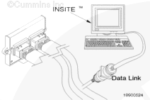
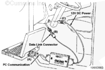
INSITE™ electronic service tool is the only Cummins supplied electronic service tool for Gas Plus Engines. Standard J1587 scan tools can be used to read fault codes and monitor some parameters, but INSITE™ electronic service tool is required to adjust parameters and monitor all parameters, among other things. For more information, refer to INSITE™ Electronic Service Tool User Manual, Bulletin 3666203.

On-line Help and the INSITE™ Electronic Service Tool User Manual – This part of INSITE™ electronic service tool contains information on how to use the INSITE™ electronic service tool application. All of the information in the user’s manual can be found in the on-line help system. This system provides context specific help through the help button in the INSITE™ electronic service tool application dialog boxes.

INSITE™ electronic service tool Security – To communicate with an engine, INSITE™ electronic service tool must have security installed. This can be installed when INSITE™ electronic service tool is installed or later. For more information on security, refer to INSITE™ electronic service tool System Administrator’s Manual, Bulletin 3885787.

INSITE™ electronic service tool Parameter Explanations:

These parameter descriptions are for Gas Plus engines only.

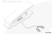
Accelerator Pedal Position – Position of the accelerator pedal. Measured in percentage 0 to 100.

Battery Voltage – Actual voltage supplied to the ECM. Please note the throttle actuator, heated oxygen sensor, and ignition control module are supplied from a switched power source. This supply voltage is not detected by the ECM.

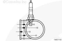
Camshaft Position Sync Counts – There are six evenly spaced pickups (one for each cylinder) and one unevenly spaced pickup (shows that the next pickup is for cylinder 1) on the cam gear. Sync counts are the number of pickups on the cam gear that pass by the engine position sensor before the seventh irregularly spaced pickup passes by it during cranking. This value must not be over 7 for one attempt at starting. If the vehicle dies or does not start on the first crank, the ignition switch must be shut off (power to ECM cut) to reset the value to zero.

Closed Loop Operation – After the first minute of operation (after the engine is started), the system must go to and remain in closed loop mode during steady state operation (idling, top of stall test, full throttle and constant load dyno test). The engine will drop out of closed loop mode when motoring (decelerating without the accelerator pedal depressed). Also, when motoring, the fuel control valve will go to 0 percent. The engine will go back into closed loop mode as soon as the accelerator pedal is depressed or when the vehicle comes to a stop.

Coolant Temperature – The temperature of the engine coolant.

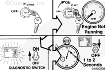
Engine Fuel Shutoff Command – Open/Closed. This is the commanded position of the fuel shutoff (not necessarily the actual mechanical position). The valve needs at least 9.5 volts to open. When the ignition is turned on, the valve will open for 2 seconds then close until engine speed is detected.

Engine Oil Pressure – Pressure measured in the oil rifle.

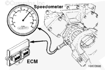
Engine Speed – This is the speed of the engine as sensed by the ECM. The ECM uses the speed read from the camshaft gear by the engine position sensor. The L Gas Plus engine uses a crankshaft sensor as back up sensor for the engine speed.

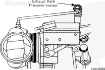
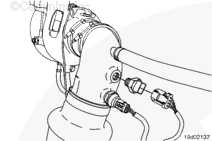
Exhaust Back Pressure is measured at the exhaust outlet connection. Note, the sensor measures the pressure in an absolute value. With no pressure applied to the sensor, it will read atmospheric pressure 101.35 kPa [14.7 psi] at sea level.

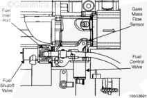
Fuel Control Valve – Percent open (not percent duty cycle) commanded to the fuel control valve. Zero percent open means the valve is closed for conditions such as over speed shutoff or motoring.

Fuel Pressure, Primary – Fuel pressure measured at the inlet to the low-pressure regulator housing. This is the pressure supplied by the high-pressure regulator.

Fuel Pressure, Secondary – Fuel pressure measured at the inlet to the mixer housing. This is the pressure supplied by the low-pressure regulator.

Gas Mass Flow Compensation – This is the amount of change (percentage duty cycle) to the fuel control valve due to the mass sensor reading. This is the correcting function that occurs when gas flow sensed does not equal gas flow commanded. This means that the gas mass flow sensor reads a different amount of fuel flow than what is being commanded.

  • A (+) positive value indicates gas flow sensed (from gas mass sensor) is less than commanded and the control system is “opening” the fuel control valve more to compensate.
  • A (-) negative value indicates gas flow sensed is more than commanded and the control system is closing the fuel control valve to compensate.

Gas Mass Flow Deviation – This is the difference between gas mass flow sensed and gas mass flow commanded. It is shown in pounds/hr. The value must remain around zero if the control system is within it’s limits.

  • A (+) positive value indicates less gas flow is being sensed than commanded.
  • A (-) negative value indicates more gas flow is being sensed than commanded.

Heated Oxygen Sensor Compensation – Percentage of fuel the heated oxygen sensor is adding/subtracting compared to it’s limit. The control system will try to bring Lambda sensed (reading from the heated oxygen sensor) closer to Lambda commanded (heated oxygen sensor deviation close to zero) by adding or subtracting fuel.

  • A (+) positive percentage means the heated oxygen sensor is sensing a rich condition and the control system is removing fuel (adding Lambda) to the gas flow commanded.
  • A (-) negative percentage means the heated oxygen sensor is sensing a lean condition and is adding fuel (removing Lambda) from the gas flow commanded.

Heated Oxygen Sensor Deviation – This is the difference between Lambda sensed and Lambda commanded. It is shown in Lambda. The value must remain around zero if the control system is within it’s limits.

  • A (+) positive value indicates a rich condition.
  • A (-) negative value indicates a lean condition.

Specific Humidity – Specific humidity is calculated using the intake manifold temperature sensor, intake manifold pressure sensor, and mixer inlet relative humidity sensor. The units are displayed in grain/pound mass of dry air. The humidity sensor can only provide a valid reading under certain engine operating conditions. The value displayed for Specific Humidity is the last value updated by the sensor. A value of 75 grains is the default and will be displayed until the engine operating conditions are met for an update.

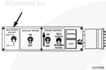
Idle Validation Status – Idle/Off-Idle status from the idle validation switches at the accelerator pedal.

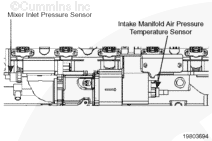
Intake Manifold Air Temperature – This is the temperature of the air in the intake manifold.

Intake Manifold Pressure – This is the pressure read by the intake manifold pressure sensor in the intake manifold. Please note, the sensor measures the pressure in an absolute value. With no pressure applied to the sensor, it will read atmospheric pressure (101.4 kPa [14.7 psi] at sea level).

Lambda – This is the unit used to measure the partial pressure of oxygen in the exhaust gas. Other Cummins natural gas engines use the term air/fuel ratio (e.g. how much fuel to air in the mixture). The higher the Lambda, the leaner the engine is running.

Mixer Inlet (Boost) Pressure – This is the pressure read by the mixer inlet pressure sensor at the air/fuel mixer assembly. Please note, the sensor measures the pressure in an absolute value. With no pressure applied to the sensor, it will read atmospheric pressure (101.4 kPa [14.7 psi] at sea level).

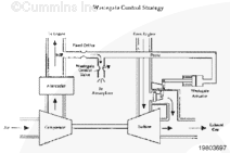
Mixer Inlet Pressure Limit – The maximum boost level allowed by the ECM before the wastegate starts to release boost pressure. Sustained boost pressures higher than the boost limit will result in an over-boost fault code.

Throttle Position – Position of the throttle plate. Measured in percentage 1 to 100.

Throttle Position Commanded – Commanded position of the throttle plate from the ECM. This value must be equal to the actual throttle position.

Wastegate Control Valve – Percentage open (not percentage duty cycle) commanded to the wastegate control valve. When the wastegate control valve is 100 percent open, the wastegate itself must be completely closed.

  • Zero percent open means the control system wants to dump boost (the valve is a normally closed valve = fail-safe for boost). Zero percent open means that the control valve vent is closed, giving pressure to the wastegate actuator and opening the wastegate to dump boost.
  • One hundred percent open means that the system wants to build boost by closing the wastegate.
  • NOTE: At and near idle, the control valve must be approximately zero percent, even though the wastegate is actually closed. This is because there is not enough pressure from the intake manifold to properly actuate the wastegate (about 55 to 83 kPa [8 to 12 psi] is required)

INSITE™ Monitor Mode

TOC

The values are based on a Gas Plus engine that is at normal operating temperature and is in closed loop mode. Before comparing monitored data to this table, be sure that the engine is at normal temperature and that the engine has been running for several minutes to ensure that it is in the closed loop mode.

This table does not include vehicle speed, ECM time, fuel shut off valve, or any other switches.

NOTE: These values are approximate. The intent of this table is to give the technician a rough idea of the expected values. These will vary between different engines, ratings, ambient temperatures, and fuel consistencies.

C Gas Plus 250-280 Horsepower INSITE™ Electronic Service Tool Parameter Value Ranges
Service Description Units Low Idle Stall
Accelerator Pedal Position % 0 100
Battery Voltage Voltage 12.5 to 14.5 12.5 to 14.5
Camshaft Position Sensor Sync Counts Counts 1 to 10 1 to 10
Closed Loop Operation None Closed Closed
Engine Coolant Temperature   77° to 91°C [170° to 195°F] 82° to 93°C [180° to 200°F]
Engine Fuel Shutoff Command On/Off On On
Engine Oil Pressure kPa [psi] 69 to 207 [10 to 30] 276 to 345 [40 to 50]
Engine Speed rpm 800 1800
Exhaust Back Pressure in – hg [psi] 0 2.5 to 5.0 [1.2 to 2.5]
Exhaust Back Pressure (Absolute) kPa [psia] 101.4 [14.7] 103 to 124 [15 to 18]
Fuel Control Value Command* % 5 to 15 35 to 75
Fuel Pressure-Primary kPa [psi] 483 to 1034 [70 to 150] 483 to 1034 [70 to 150]
Fuel Pressure-Secondary kPa [psi] 310 to 483 [45 to 70] 310 to 483 [45 to 70]
Gas Mass Flow Compensation % ±10 ±25
Gas Mass Flow Deviation lb/hr ±3 ±3
Heated Oxygen Sensor Compensation % ±60 ±60
Heated Oxygen Sensor Deviation Lambda ±0.1 ±0.1
Intake Manifold Air Temperature   32° to 56°C [90° to 130°F] 32° to 56°C [90° to 130°F]
Intake Manifold Pressure kPa [psia] 101 to 114 [14.7 to 16.5] 193 to 228 [28 to 33]
Mixer Inlet Pressure kPa [psia] 101 to 114 [14.7 to 16.5] 193 to 228 [28 to 33]
Mixer Inlet Pressure Limit Throttle Position kPa [psia] 101 to 114 [14.7 to 16.5] 193 to 228 [28 to 33]
% 5 to 20 98 to 100
Throttle Position Command % 5 to 20 98 to 100
Specific Humidity grains/pound mass of dry air 20 to 150 20 to 150
Wastegate Control Valve Command* % 0 to 1 45 to 84
B Gas International (B Gas International) 150 to 230 Horsepower INSITE™ Electronic Service Tool Parameter Value Ranges
Service Description Units Low Idle (700 to 800 rpm) Stall (2000 rpm)l
Accelerator Pedal Position % 0 100
Battery Voltage Voltage 12.5 to 14.5 12.5 to 14.5
Camshaft Position Sensor Sync Counts Counts 1 to 10 1 to 10
Closed Loop Operation None Closed Closed
Engine Coolant Temperature °C [°F] 77° to 91°C [170° to 195°F] 82° to 93°C [180° to 200°F]
Engine Fuel Shutoff Command On/Off On On
Engine Speed rpm 800 2000
Fuel Control Value Command* % 5 to 15 30 to 70
Fuel Pressure-Secondary kPa [psi] 310 to 414 [45 to 60] 310 to 414 [45 to 60]
Gas Mass Flow Compensation % ±10 ±25
Gas Mass Flow Deviation lb/hr ±3 ±3
Heated Oxygen Sensor Compensation % ±80 ±80
Heated Oxygen Sensor Deviation Lambda ±0.1 ±0.1
Intake Manifold Air Temperature °C [°F] 32° to 56°C [90° to 130°F] 32° to 56°C [90° to 130°F]
Intake Manifold Pressure kPa [psia] 28 to 103 [4 to 15] 138 to 221 [20 to 32]
B Gas Plus 195 to 230 Horsepower INSITE™ Electronic Service Tool Parameter Value Ranges
Service Description Units Low Idle (700 to 800 rpm) Stall (2000 rpm)
Accelerator Pedal Position % 0 100
Battery Voltage Voltage 12.5 to 14.5 12.5 to 14.5
Camshaft Position Sensor Sync Counts Counts 1 to 10 1 to 10
Closed Loop Operation None Closed Closed
Engine Coolant Temperature Degrees Fahrenheit 76.6° to 91°C [170° to 195°F] 82° to 93°C [180° to 200°F]
Engine Fuel Shutoff Command On/Off On On
Engine Oil Pressure kPa [psi] 69 to 207 [10 to 30] 276 to 345 [40 to 50]
Engine Speed rpm 800 2000
Exhaust Back Pressure in-hg [psi] 0 2.5 to 5.0 [1.2 to 2.5]
Exhaust Back Pressure Absolute kPa [psia] 101.4 [14.7] 103 to 124 [15 to 18]
Fuel Control Valve Command % 5 to 15 30 to 70
Fuel Pressure-Primary kPa [psi] 414 to 1034 [60 to 150] 414 to 1034 [60 to 150]
Fuel Pressure-Secondary kPa [psi] 310 to 414 [45 to 60] 310 to 414 [45 to 60]
Gas Mass Flow Compensation % ± 10 ± 25
Gas Mass Flow Deviation lb/hr ± 3 ± 3
Heated Oxygen Sensor Compensation % ± 80 ± 80
Heated Oxygen Sensor Deviation Lambda ± 0.1 ± 0.1
Intake Manifold Air Temperature   32° to 56°C [90° to 130°F] 32° to 56°C [90° to 130°F]
Intake Manifold Pressure kPa [psia] 28 to 103 [4 to 15] 138 to 221 [20 to 32]
Mixer Inlet Pressure kPa [psia] 83 to 103 [12 to 15] 138 to 228 [20 to 33]
Mixer Inlet Pressure Limit kPa [psia] 83 to 103 [12 to 15] 138 to 228 [20 to 33]
Throttle Position % 5 to 20 98 to 100
Throttle Position Command % 5 to 20 98 to 100
Specific Humidity Grains/pound mass of dry air 20 to 150 20 to 150
Wastegate Control Valve Command* % 0 to 1 20 to 84

* All values are based on 14.7 psi atmospheric pressure

B LPG Plus 195 Horsepower INSITE™ Electronic Service Tool Parameter Value Ranges
Service Description Units Low Idle (700 to 800 rpm) Stall (2000 rpm)
Accelerator Pedal Position % 0 100
Battery Voltage Voltage 12.5 to 14.5 12.5 to 14.5
Camshaft Position Sensor Sync Counts Counts 1 to 10 1 to 10
Closed Loop Operation None Closed Closed
Engine Coolant Temperature   77° to 91°C [170° to 195°F] 82° to 93°C [180 to 200°F]
Engine Fuel Shutoff Command On/Off On On
Engine Oil Pressure kPa [psi] 69 to 207 [10 to 30] 276 to 345 [40 to 50]
Engine Speed rpm 800 2000
Exhaust Back Pressure in-hg [psi] 0 2.5 to 5.0 [1.2 to 2.5]
Exhaust Back Pressure (Absolute) kPa [psia] 101.4 [14.7] 103 to 124 [15 to 18]
Fuel Control Valve Command % 5 to 15 30 to 70
Fuel Pressure-Primary kPa [psi] 276 to 1999 [40 to 290] 276 to 1999 [40 to 290]
Fuel Pressure-Secondary kPa [psi] 159 to 221 [23 to 32] 159 to 221 [23 to 32]
Gas Mass Flow Compensation % ± 10 ± 25
Gas Mass Flow Deviation lb/hr ± 3 ± 3
Heated Oxygen Sensor Compensation % ± 80 ± 80
Heated Oxygen Sensor Deviation Lambda ± 0.1 ± 0.1
Intake Manifold Air Temperature Degrees Celsius 32° to 56°C [90° to 130°F] 32° to 56°C [90° to 130°F]
Intake Manifold Pressure kPa [psia] 28 to 103 [4 to 15] 138 to 221 [20 to 32]
Mixer Inlet Pressure kPa [psia] 83 to 103 [12 to 15] 138 to 228 [20 to 33]
Mixer Inlet Pressure Limit kPa [psia] 83 to 103 [12 to 15] 138 to 228 [20 to 33]
Throttle Position % 5 to 20 98 to 100
Throttle Position Command % 5 to 20 98 to 100
Specific Humidity Grains/pound mass of dry air 20 to 150 20 to 150
Wastegate Control Valve Command % 0 to 1 20 to 85
L Gas Plus 320 Horsepower INSITE™ Electronic Service Tool Parameter Value Ranges
Service Description Units Low Idle Stall
Accelerator Pedal Position % 0 100
Battery Voltage Voltage 12.5 to 14.5 12.5 to 14.5
Camshaft Position Sensor Sync Counts Counts 1 to 10 1 to 10
Closed Loop Operation None Closed Closed
Engine Coolant Temperature   77° to 91°C [170° to 190°F] 82° to 93°C [180° to 200°F]
Engine Fuel Shutoff Command On/Off On On
Engine Oil Pressure kPa [psia] 172 to 310 [25 to 45] 379 to 488 [55 to 65]
Engine Speed rpm 800 1800
Exhaust Back Pressure kPa [psia] 101.4 [14.7] 103 to 124 [15 to 18]
Fuel Control Valve Command % 5 to 15 35 to 75
Fuel Pressure-Primary kPa [psi] 276 to 1999 [40 to 290] 276 to 1999 [40 to 290]
Fuel Pressure-Secondary kPa [psi] 159 to 221 [23 to 32] 159 to 221 [23 to 32]
Gas Mass Flow Compensation % ± 10 ± 25
Gas Mass Flow Deviation lb/hr ± 3 ± 3
Heated Oxygen Sensor Compensation % ± 60 ± 60
Heated Oxygen Sensor Deviation Lambda ± 0.1 ± 0.1
Intake Manifold Air Temperature   32° to 56°C [90° to 130°F] 32° to 56°C [90° to 130°F]
Intake Manifold Pressure kPa [psia] 34 to 101 [5 to 14.7] 262 to 310 [38 to 45]
Mixer Inlet Pressure kPa [psia] 101 to 114 [14.7 to 16.5] 262 to 310 [38 to 45]
Mixer Inlet Pressure Limit kPa [psia] 101 to 114 [14.7 to 16.5] 262 to 310 [38 to 45]
Throttle Position % 5 to 20 98 to 100
Throttle Position Command % 5 to 20 98 to 100

Open Loop Mode Lock-In Test – Open Loop Mode Lock-in is a useful feature for troubleshooting fuel system problems. This feature allows the technician to put the engine into open loop mode. In open loop mode, the engine is not using the heated oxygen sensor. This test can help determine whether a performance issue is associated with the heated oxygen sensor.

Fuel System Adaptive Learn – The Gas Plus engines have the ability to learn the conditions in which it functions. This type of feature was implemented to enhance the performance of the engine and increase customer satisfaction. The feature is available on all Gas Plus engines.

To use this feature, the Gas Plus engines utilizes the various sensors in the fuel system to learn and adjust the open loop fueling of the engine.

The ECM, when initially programmed, has default tables that attempt to provide the proper fuel rate to the engine. Due to various open loop errors, the default tables can possibly not provide the best performance for the operating conditions of the engine.

The ECM is able to learn the required corrections to the open loop system using the sensors on the engine. These learned corrections are added to the base tables in the ECM, resulting in a more accurate open loop fueling estimation. The result is better open loop performance, better transient response of the fuel system, and reduced variability from unit to unit.

When the following components are replaced during a repair, the fuel system table will need to be reset using INSITE™ electronic service tool.

  • Fuel control valve
  • Gas mass flow sensor
  • Heated oxygen sensor

Last Modified:  20-Jan-2005