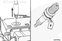
Remove the spark plug. Refer to Procedure 013-016 in the following manuals, Troubleshooting and Repair Manual C8.3G (Natural Gas) Engines, Bulletin 3666206, Troubleshooting and Repair Manual B5.9G, B5.9LPG, B Gas Plus, and B LPG Plus Engines, Bulletin 3666164, Troubleshooting and Repair Manual L10G (Natural Gas) Engines, Bulletin 3666207, Troubleshooting and Repair Manual Generator Set QSK19G Series Engines, Bulletin 4021372, Troubleshooting and Repair Manual QSV81G and QSV91G Series Engines, Bulletin 4021314, Troubleshooting and Repair Manual Generator Set QSK45G and QSK60G Series Engines, Bulletin 4021396, and the Mechanical Gas Fuel System Master Repair Manual, Bulletin 4021404.
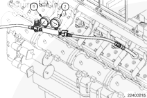
Install the leak test adapter, Part Number 4918177 (14-mm spark plug threads) or Part Number 4918178 (18-mm spark plug threads) and hand tighten into the spark plug mounting hole.
Wear appropriate eye and face protection when using compressed air. Flying debris and dirt can cause personal injury.
The crankshaft breather is not to be obstructed during this test, do not install plugs or orifices as sometimes used in traditional blow-by tests.
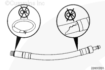
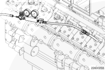
Close the ball valve on the differential cylinder pressure tester, Part Number 3824223. Connect the differential cylinder pressure tester outlet hose to the fitting on the leak test adapter.
Wear appropriate eye and face protection when using compressed air. Flying debris and dirt can cause personal injury.
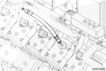
Connect the differential cylinder pressure tester inlet hose to shop air.
Open the differential pressure tester ball valve slowly, taking careful note of any crankshaft rotation. If any rotation is apparent, the piston will not be correctly positioned in the cylinder. If the piston is correctly positioned in the cylinder and the engine crankshaft still rotates, the engine barring mechanism must be locked out to prevent engine rotation.
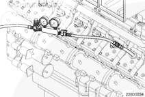
Make certain that there are no leaks at any connection joint.
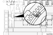
Pressurize the cylinder and adjust the regulator on the differential pressure tester until gauge (1) indicates 689 kPa [100 psi]. When the reading on gauge (2) has stabilized, record the pressure reading of both gauges and record the cylinder number and bank.
If at any time during the test the reading on gauge (2) is not stable, repeat the positioning procedure.
The leakdown test can be used to determine the relative condition of the cylinder when compared to other cylinders in the engine. The leakdown test can also help diagnose the source of leakage or blowby. This includes, but is not limited to, air flow from the breather (worn cylinder), air flow in the intake or exhaust manifold (leaking valves) or air bubbles in the coolant (leaking cylinder head gasket, cylinder head crack or cylinder block crack).
Before taking any action based on leakdown test results, repeat the leakdown test for the suspect cylinder and compare to the original results. Factory leakdown limits will not be established, cautious judgment must be used before replacing parts or taking any action due to results from the leakdown test.
Additionally, the test results subject to comparison need to be obtained within a relatively short period of time. Leakdown test results are expected to vary depending on engine temperature. Because of this, comparing leakdown results from different engines is not recommended.
Remove the differential pressure tester and leak test adapter.
Install the spark plug. Refer to Procedure 013-016 in the following manuals, Troubleshooting and Repair Manual C8.3G (Natural Gas) Engines, Bulletin 3666206, Troubleshooting and Repair Manual B5.9G, B5.9LPG, B Gas Plus, and B LPG Plus Engines, Bulletin 3666164, Troubleshooting and Repair Manual L10G (Natural Gas) Engines, Bulletin 3666207, Troubleshooting and Repair Manual Generator Set QSK19G Series Engines, Bulletin 4021372, Troubleshooting and Repair Manual QSV81G and QSV91G Series Engines, Bulletin 4021314, Troubleshooting and Repair Manual Generator Set QSK45G and QSK60G Series Engines, Bulletin 4021396, and the Mechanical Gas Fuel System Master Repair Manual, Bulletin 4021404.
Hello, I'm Jack, a diesel engine fan and a blogger. I write about how to fix and improve diesel engines, from cars to trucks to generators. I also review the newest models and innovations in the diesel market. If you are interested in learning more about diesel engines, check out my blog and leave your feedback.
View all posts by Jack


 WARNING
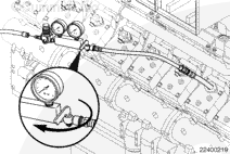
;)
;)
;)
;)
;)
;)
;)
;)
;)
;)
;)
;)
;)
;)
;)
;)