CM850 Electronic Control System – 019-052   Idle Adjust Switch

General Information

TOC

The idle adjust switch is located on the control panel and has three settings, RPM+, RPM-, and OFF. The rocker switch is used to activate or disable the idle adjust operation. The idle adjust circuit consists of the RPM+ and RPM- signal lines, switch common ground and the rocker switch.

 
SMALL | MEDIUM | LARGE

Resistance Check

TOC

If INSITE™ is available, monitor the switch for proper operation. If not, follow the troubleshooting procedures in this section.

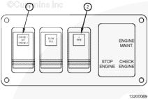
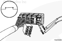
Locate and remove the idle adjust switch from the connector.

Adjust the multimeter to measure resistance.

Touch the multimeter probes to the RPM+ signal switch prong (3) and the battery ground prong switch prong (2).

Turn the switch to the OFF position and measure the resistance. The multimeter must show an open circuit (100k ohms or more).

If the circuit is not open, the switch has failed. Replace the switch.

Touch the multimeter probes to the RPM- signal switch prong (1) and the battery ground prong switch prong (2).

Turn the switch to the OFF position and measure the resistance. The multimeter must show an open circuit (100K ohms or more).

If the circuit is not open, the switch has failed. Replace the switch.

SMALL | MEDIUM | LARGE
   

Check for Short Circuit to Ground

TOC

Touch the multimeter probes to the RPM+ signal switch prong (3) and the battery ground prong switch prong (2).

Hold the switch depressed to the RPM+ position and measure the resistance. The multimeter must show an closed circuit (10 ohms or less).

If the circuit is not closed, the switch has failed. Replace the switch.

Touch the multimeter probes to the RPM- signal switch prong (1) and the battery ground prong switch prong (2).

Hold the switch depressed to the RPM- position and measure the resistance. The multimeter must show an closed circuit (10 ohms or less).

If the circuit is not closed, the switch has failed. Replace the switch.

 
SMALL | MEDIUM | LARGE
   

Check for Short Circuit from Pin to Pin

TOC

Check for a short circuit from pin to pin.

Touch the multimeter probe to the RPM+ switch signal prong (3). Touch the other multimeter probe to the RPM- switch signal prong (1).

Turn the cruise control switch to the OFF position.

The multimeter must show an open circuit (100k ohms or more).

If the circuit is not open, there is a short circuit between the RPM+ and RPM- signal lines. Replace the switch.

 
SMALL | MEDIUM | LARGE
Last Modified:  10-Mar-2005