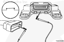
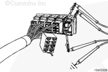
Disconnect the Smart Multiplex module connector from the Smart Multiplex module.
Touch the probe to the synchronization switch signal pin of the Smart Multiplex module connector. Touch the other probe to the unswitched battery
(-) pin of the Smart Multiples module connector.
Move the switch to the ON position. The multimeter must show a closed circuit (10 ohms or less). If the circuit is not closed, inspect the synchronization switch for an open circuit. Refer to Procedure 019-270.
If the resistance is within specification, the synchronization switch circuit must be checked for a short circuit to ground, and a short circuit from terminal to terminal.
Disconnect the Smart Multiplex module connector from the Smart Multiplex module.
Adjust the multimeter to measure resistance.
Touch the multimeter probe to the synchronization switch signal pin of the Smart Multiplex module connector. Touch the other probe to the unswitched battery (-) pin of the Smart Multiplex module connector.
Move the synchronization switch to the OFF position.
Measure the resistance.
The multimeter must show an open circuit (100k ohms or more). If the circuit is not open, there is a short circuit to ground in the cruise control circuit, provided that the switch has been previously checked.
Repair or replace the signal wire connected to the synchronization switch and/or the signal wire connected to the Smart Multiples module.
Check for a short circuit from pin to pin. Set all switches to the C-Cruise Switch control module to the OFF position. Touch the multimeter probe to the synchronization switch signal pin on the Smart Multiplex module connector. Touch the other probe to all of the other signal pins of the Smart Multiplex module connector in succession.
The multimeter must show an open circuit (100k ohms or more) for each pin check.
If the circuit is not open, there is a short circuit between the synchronization circuit and any pin that shows a closed circuit, provided the switch has previously checked.
Repair or replace the appropriate wire in the Smart Multiplex module harness or C-Cruise switch panel harness.
Hello, I'm Jack, a diesel engine fan and a blogger. I write about how to fix and improve diesel engines, from cars to trucks to generators. I also review the newest models and innovations in the diesel market. If you are interested in learning more about diesel engines, check out my blog and leave your feedback.
View all posts by Jack
;)
;)
;)
;)
;)
;)