The position sensor pins can be bent if the engine harness connector is mated to the sensor connector at an angle. Therefore, the engine harness connector must be inserted straight into the position sensor connector to reduce the possibility of damaging the pins. Bent pins will result in poor engine performance and intermittent fault codes.
CAUTION
Do not use connector grease on the turbocharger position sensor connector. Use of connector grease can cause damage to the turbocharger control valve and low engine performance.
The turbocharger position sensor outputs a voltage signal to the ECM. The ECM converts this signal into a percentage, 0 to 100 percent, indicating variable geometry turbocharger position. A fully closed turbocharger is equivalent to 100 percent.
The turbocharger position sensor is located on the variable geometry turbocharger actuator assembly.
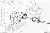
There are two types of position sensors. The original position sensor has the connector molded into the sensor (shown in the diagram). The new hull effect position sensor has a pigtail harness connected to the sensor.
The position sensor pins can be bent if the engine harness connector is mated to the sensor connector at an angle. Therefore, the engine harness connector must be inserted straight into the position sensor connector to reduce the possibility of damaging the pins. Bent pins will result in poor engine performance and intermittent fault codes.
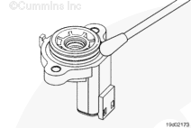
Rotate the internal hub of the sensor so it will align with the flat spot on the shaft.
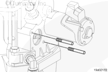
Guide pins, Part Number 3165138, are necessary for proper alignment between the position sensor and the housing. Improper alignment will result in damage to the sensor.
Insert alignment pins into the capscrew holes in the housing.
Do not use connector grease on the turbocharger position sensor connector. Use of connector grease can cause damage to the turbocharger control valve and low engine performance.
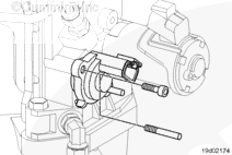
Connect the engine harness connector to the sensor. Push the connectors together until they lock.
Inspect the wiring harness and connector for excessive tension.
If excessive tension is present, determine the source and relieve the tension on the circuit.
Hello, I'm Jack, a diesel engine fan and a blogger. I write about how to fix and improve diesel engines, from cars to trucks to generators. I also review the newest models and innovations in the diesel market. If you are interested in learning more about diesel engines, check out my blog and leave your feedback.
View all posts by Jack
 CAUTION
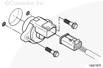


;)
;)
;)
;)
;)
;)
;)
;)
;)
;)