View Related Topic
Engine Views
|
TOC |
With CM850
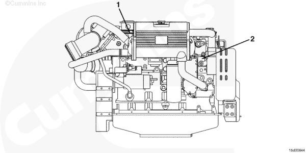
The following illustrations provide the locations of the major external engine components, filters, and other service and maintenance points. Some external components will be at different locations for different engine models.
NOTE: The illustrations are
only a reference to show a typical engine.
|
|
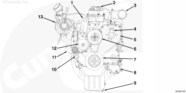
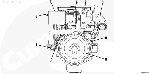
| Front View (ISC, QSC8.3, ISL, and QSL9) |
- Engine lifting bracket
- Crankcase breather
- Air intake connection
- Engine oil fill
- Front gear cover
- Fan pulley
- Vibration Damper
- Starter
- Engine oil pan drain plug
- Automatic belt tensioner
- Coolant inlet connection
- Water pump
- Turbocharger (Variable Geometry Turbocharger shown)
|
|
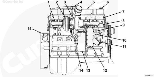
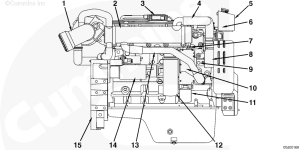
| Exhaust Side View (ISC, QSC8.3, ISL, and QSL9) |
- Exhaust manifold
- Turbocharger (variable geometry turbocharger shown)
- Variable geometry turbocharger actuator
- Crankcase breather
- Rocker lever cover
- Engine oil fill
- Rocker lever housing
- Coolant outlet connection
- Coolant temperature sensor
- Coolant heater port
- Coolant inlet connection
- Lubricating oil cooler
- Lubricating oil filter
- Dipstick location
- Flywheel housing.
|
|
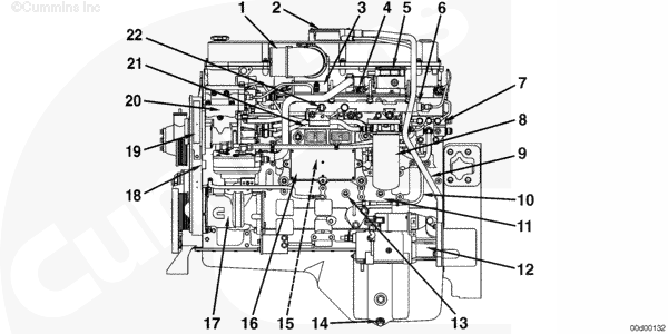
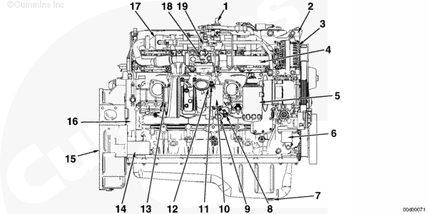
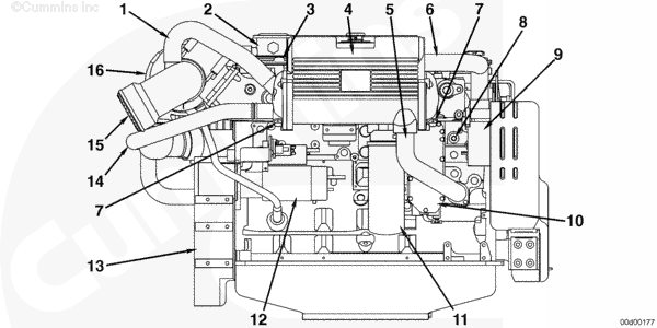
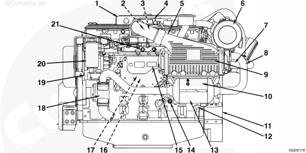
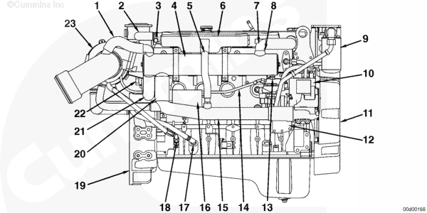
| Intake Side View (ISC, QSC8.3, ISL, and QSL9) |
- Air intake connection
- Crankcase breather
- Intake air heater
- Intake manifold pressure and temperature sensor
- Turbocharger control valve
- Fuel rail
- Fuel drain manifold
- Fuel filter
- Crankcase breather draft tube
- Crankcase breather oil drain tube
- Crankshaft speed sensor
- Starter
- Lubricating oil pressure sensor
- Engine oil drain plug
- Fuel lift pump (behind ECM)
- Electronic control module (ECM)
- Air compressor
- Camshaft speed sensor
- Engine data plate
- High-pressure fuel pump
- Ambient air pressure sensor
- Fuel rail pressure sensor.
|
|
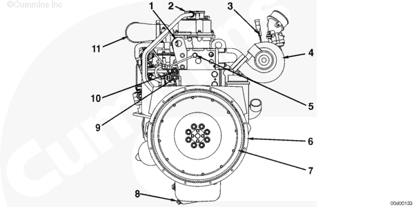
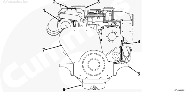
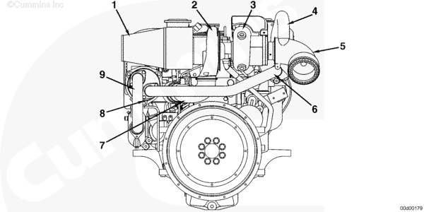
| Rear View (ISC, QSC8.3, ISL, and QSL9) |
- Engine lifting bracket
- Crankcase breather
- Turbocharger speed sensor (
only on variable geometry turbochargers)
- Turbocharger (variable geometry turbocharger shown)
- Injector drain line connection
- Flywheel housing
- Flywheel
- Engine oil drain plug
- OEM fuel supply line connection
- OEM fuel drain line connection
- Air intake connection.
|
|
| Top View (ISC, QSC8.3, ISL, and QSL9) |
- Turbocharger compressor inlet temperature sensor
- Turbocharger air inlet
- Turbocharger air outlet
- Turbocharger exhaust outlet
- Turbocharger actuator air line
- Crankcase breather
- Flywheel housing
- Crankcase breather oil drain tube
- Crankcase breather draft tube
- Turbocharger control valve
- Fuel filter bracket
- Air inlet connection
- High-pressure fuel pump
- Crankcase pressure sensor (
only on recreational vehicles)
- Engine oil fill
- Coolant outlet connection
- Coolant inlet connection.
ISB
|
|
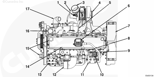
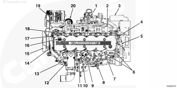
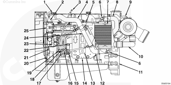
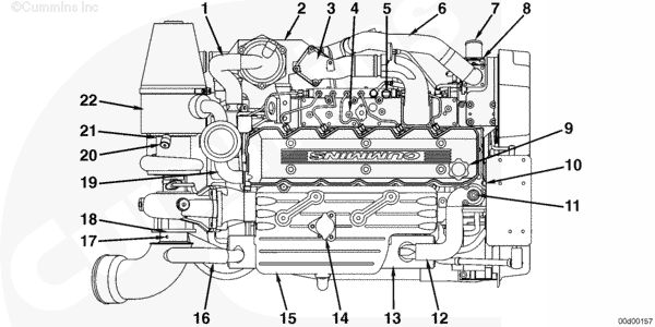
| Intake Side View (CM850 Electronic Control Module) |
- Exhaust pressure sensor
- Fuel rail pressure relief valve
- Fuel rail
- Intake manifold pressure sensor
- Intake temperature sensor
- Electronic fuel control (EFC) actuator
- Bosch® fuel pump
- Air compressor
- Flywheel housing
- Oil pressure switch
- Fuel filter
- Fuel inlet to cooling plate
- Oil pan drain plug
- Barometric pressure sensor
- Engine speed sensor (crankshaft)
- Electronic control module
- Engine speed sensor (camshaft)
- Air intake inlet
- EGR temperature sensor
- Fuel heater
- Fuel rail pressure sensor.
|
|
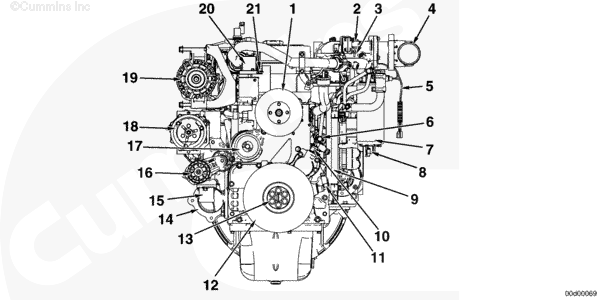
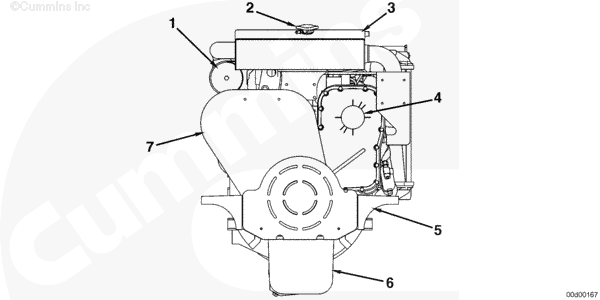
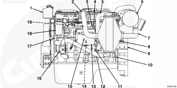
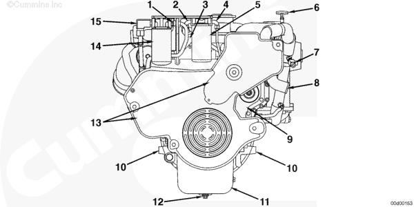
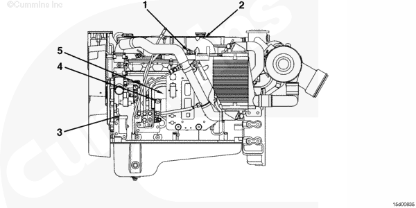
| Front View (CM850 Electronic Control Module) |
- Fan drive
- EGR differential pressure sensor
- EGR temperature sensor
- Air inlet
- Fuel heater
- Fuel lift pump
- Fuel filter
- Water-in-fuel sensor
- Electronic control module
- Engine speed sensor (camshaft)
- Engine speed sensor (crankshaft)
- Vibration damper
- Fan or PTO drive flange mounting
- Starter
- Coolant inlet
- Belt tensioner
- Water pump
- Freon compressor
- Alternator
- Coolant outlet
- Coolant temperature sensor.
|
|
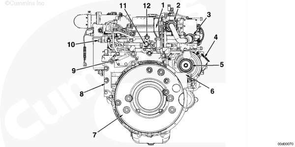
| Rear View (CM850 Electronic Control Module) |
- Breather tube (valve cover to gear housing)
- EGR cooler
- EGR valve
- Air outlet from turbocharger
- Turbocharger exhaust outlet
- Flywheel housing
- Flywheel
- Gear housing
- Crankcase breather
- Fuel out (return to tank)
- Coolant connection for air compressor
- Fuel return line.
|
|
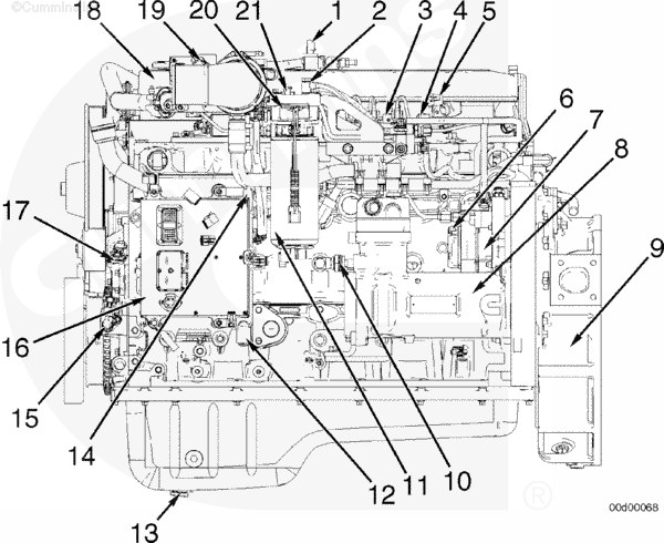
| Exhaust Side View (CM850 Electronic Control Module) |
- Exhaust pressure sensor
- Coolant outlet
- Alternator
- Exhaust manifold
- Oil filter
- Coolant inlet
- Oil pan drain plug
- Turbocharger position sensor
- Turbocharger actuator
- Turbocharger compressor inlet
- Compressor inlet temperature sensor
- Turbocharger speed sensor
- Turbocharger exhaust outlet
- Starter
- Flywheel housing
- Gear housing
- EGR cooler
- EGR valve
- EGR actuator.
|
|
| Top View (CM850 Electronic Control Module) |
- EGR valve
- EGR cooler
- Starter
- Breather tube (valve cover to gear housing)
- Air compressor cooling connection
- High-pressure fuel lines
- Intake temperature sensor
- Fuel rail
- Intake manifold pressure sensor
- Fuel rail pressure relief valve
- Fuel rail pressure sensor
- EGR temperature sensor
- EGR differential pressure sensor
- Tone wheel
- Vibration damper
- Oil fill cap
- Coolant temperature sensor
- Coolant outlet
- Alternator
- Oil filter.
Marine Applications
|
|
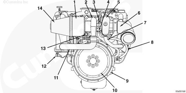
| QSL Front View (CM850 Electronic Control Module) |
- Heat exchanger
- Coolant fill cap
- Expansion tank
- Timing case cover
- Engine mounting bracket
- Oil pan
- Belt and fan guard.
|
|
| QSL Port View (CM850 Electronic Control Module) |
- Expansion tank
- Aftercooler air outlet
- Intake manifold temperature sensor
- Intake manifold pressure sensor
- Aftercooler seawater outlet
- Air cleaner or filter
- Aftercooler air inlet
- Aftercooler housing
- SAE number 1 flywheel housing
- Crankshaft speed sensor
- Oil pressure sensor
- Aftercooler seawater inlet
- Engine control module (ECM)
- Fuel lift pump (behind ECM)
- SIM module
- Seawater pump
- Camshaft position sensor
- Fuel filter
- Fuel rail pressure sensor (behind aftercooler air outlet).
|
|
| QSL Starboard View (CM850 Electronic Control Module) |
- Water cooled exhaust elbow
- Heat exchanger
- Crankcase breather
- Heat exchanger coolant inlet
- Expansion tank
- Coolant level sensor
- Zinc anode
- Alternator
- Coolant temperature sensor
- Lubricating oil cooler
- Coolant filter
- Lubricating oil filter
- Heat exchanger coolant outlet
- Starter motor
- SAE number 1 flywheel housing.
|
|
| Rear View QSL (CM850 Electronic Control Module) |
- Air cleaner and filter
- Turbocharger compressor side
- Turbocharger exhaust turbine side
- Water cooled exhaust elbow
- SAE number 1 flywheel housing
- Flywheel
- Aftercooler air inlet
- Aftercooler zinc anode.
|
|
| Front View (QSC) (CM850 Electronic Control Module) |
- Heat exchanger
- Coolant fill cap
- Expansion tank
- Timing case cover
- Engine mounting bracket
- Oil pan
- Belt and pulley guard.
|
|
| QSC Starboard View (CM850 Electronic Control Module) |
- Seawater outlet from heat exchanger
- Vacuum regulator for air filter
- Coolant level sensor
- Expansion tank
- Coolant outlet from heat exchanger
- Coolant inlet to heat exchanger
- Zinc anodes
- Coolant temperature sensor
- Alternator
- Lubricating oil cooler
- Lubricating oil filter
- Starter motor
- SAE number 1 flywheel housing
- Seawater inlet to heat exchanger
- Exhaust elbow
- Turbocharger.
|
|
| QSC Port View (CM850 Electronic Control Module) |
- Expansion tank
- Intake manifold temperature sensor (behind aftercooler air outlet)
- Intake manifold pressure sensor (behind aftercooler air outlet
- Crankcase breather
- Aftercooler air outlet
- Air cleaner or filter
- Aftercooler seawater outlet
- Aftercooler seawater inlet
- Aftercooler housing
- Fuel cooler
- SAE number 1 flywheel housing
- Crankshaft speed sensor
- Gear cooler
- Oil pressure sensor
- Engine control module (ECM)
- Fuel lift pump (behind ECM)
- SIM module
- Seawater Pump
- Camshaft position sensor
- Fuel filter
- Fuel rail pressure sensor.
|
|
| QSC Rear View (CM850 Electronic Control Module) |
- Air cleaner or filter
- Turbocharger compressor side
- Turbocharger exhaust side
- Heat exchanger seawater outlet
- Seawater cooled exhaust elbow
- Heat exchanger seawater inlet
- Aftercooler air inlet
- Aftercooler drain valve.
- Aftercooler seawater inlet
|
|
| QSB Front View (CM850 Electronic Control Module) |
- Lubricating oil filter head outlet
- Fuel filter head outlet to high pressure fuel pump
- Coolant temperature sensor
- Fuel filter head inlet from lift pump
- Fuel filter
- Lubricating oil dipstick
- Fuel return from fuel cooler to tank
- Sea water pump inlet
- Timing case cover
- Mounting brackets
- Oil pan
- Lubricating oil drain
- Belt and pulley guards
- Lubricating oil filter
- Lubricating oil filter head inlet.
|
|
| QSB Port View (CM850 Electronic Control Module) |
- Engine oil fill
- Sea water pump outlet
- Lubricating oil level gauge
- Sea water supply to fuel cooler
- Intake manifold pressure and air temperature sensor
- Aftercooler zinc anode (2)
- Aftercooler housing
- Aftercooler sea water outlet
- Turbocharger
- Aftercooler air inlet
- Flywheel housing
- Aftercooler sea water inlet
- Electronic control module (ECM)
- Fuel lift pump (behind ECM cooling plate)
- Fuel inlet connection
- Fuel return from injector
- Fuel supply to lift pump
- Fuel return from fuel rail pressure relief valve
- Fuel return from high pressure fuel pump
- Crankshaft speed sensor
- Camshaft speed sensor
- Oil pressure sensor
- Fuel pump
- Fuel cooler
- Sea water pump.
|
|
| QSB Starboard View (CM850 Electronic Control Module) |
- Sea water outlet
- Closed crankcase breather system hose
- Crankcase breather tube banjo connection
- Heat exchanger
- Engine coolant fill line
- Expansion tank
- Coolant level sensor
- Heat exchanger engine coolant inlet
- Lubricating oil filter
- Alternator
- Belt and pulley guard
- Lubricating oil cooler
- Zinc anode
- Turbocharger oil supply line
- Coolant return junction tube
- Starting motor
- Turbocharger oil drain line
- Closed crankcase breather oil drain line
- Flywheel housing
- Heat exchanger engine coolant outlet
- Heat exchanger sea water inlet
- Marine gear oil cooler
- Turbocharger
|
|
| QSB Rear View (CM850 Electronic Control Module) |
- Closed crankcase breather system
- Turbocharger, compressor side
- Turbocharger oil supply
- Turbocharger oil drain
- Turbocharger, turbine side
- Heat exchanger (behind exhaust outlet)
- Turbocharger coolant outlet
- Closed crankcase breather oil drain tube
- Flywheel housing
- Flywheel
- Aftercooler air inlet
- Aftercooler zinc anode
- Marine gear oil cooler
- Air cleaner and filter.
|
|
| QSB Top View (CM850 Electronic Control Module) |
- Aftercooler seawater outlet
- Aftercooler housing
- Intake air connection from aftercooler to intake manifold
- Intake manifold pressure and temperature port
- Fuel rail pressure sensor
- Sea water supply to fuel cooler
- Sea water pump inlet
- Sea water pump
- Engine oil fill
- Coolant temperature sensor
- Coolant pressure side vent petcock
- Heat exchanger engine coolant inlet
- Heat exchanger
- Coolant fill neck
- Expansion tank
- Sea water outlet from heat exchanger
- Exhaust temperature and back pressure port
- Exhaust outlet connection
- Closed crankcase breather blow-by connection
- Air inlet restriction indicator
- Air cleaner connection
- Closed crankcase breather/air cleaner assembly.
|
|
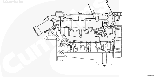
| QSB5.9 Marine Sensors Port View |
- Rail fuel pressure sensor
- Intake manifold pressure sensor
- Engine position/speed sensor
- Engine oil pressure sensor
- Fuel lift pump – 12-VDC and 24-VDC (behind ECM cooling plate).
|
|
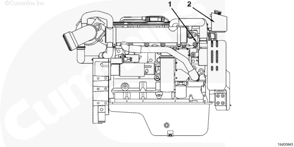
| QSB5.9 Marine sensor Starboard View |
- Coolant level sensor
- Coolant temperature sensor.
|
|
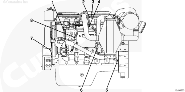
| QSL9 Marine Sensors Port View |
- Fuel pump actuator high pressure
- Intake manifold temperature sensor
- Intake manifold pressure sensor
- Rail fuel pressure sensor
- Crankshaft position sensor
- Engine oil pressure sensor
- Camshaft position sensor
- Fuel lift pump – 12-VDC and 24-VDC (behind the ECM cooling plate)
|
|
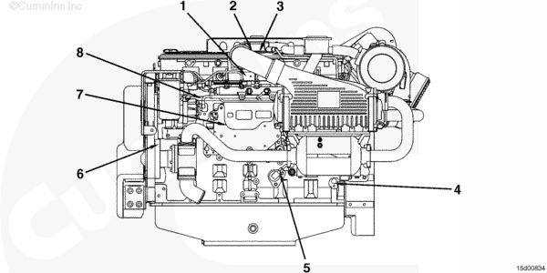
| QSL9 Marine Sensors Starboard View |
- Coolant temperature sensor (behind alternator)
- Coolant level sensor (rear of expansion tank).
- Rail fuel pressure sensor
- Intake manifold pressure sensor (behind aftercooler air outlet)
- Intake manifold temperature sensor (behind aftercooler air outlet)
- Crankshaft position sensor
- Engine oil pressure sensor
- Camshaft position sensor (front gear housing)
- Fuel lift pump – 12-VDC and 24-VDC (behind ECM cooling plate)
- Fuel pump actuator, high pressure.
- Coolant level sensor (rear of expansion tank)
- Coolant temperature sensor (behind alternator).
|
Last Modified: 26-Nov-2008
Published by Jack
Hello, I'm Jack, a diesel engine fan and a blogger. I write about how to fix and improve diesel engines, from cars to trucks to generators. I also review the newest models and innovations in the diesel market. If you are interested in learning more about diesel engines, check out my blog and leave your feedback.
View all posts by Jack
;)
;)
;)
;)
;)
;)
;)
;)
;)
;)
;)
;)
;)
;)
;)
;)
;)
;)
;)
;)
;)
;)
;)
;)
;)
;)
;)
;)
;)
;)
;)
;)
;)
;)
;)
;)
;)
;)
;)
;)
;)
;)
;)
;)
;)
;)
;)
;)
;)
;)
;)
;)
;)
;)
;)
;)
;)
;)