|
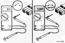
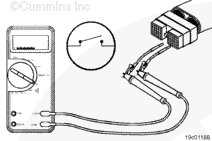
Move the engine brake ON/OFF switch to the ON position. Move the engine brake level switch to position number 1 for a six-position switch or to position number 2 for a three-position switch. The multimeter
must show a closed circuit (10 ohms or less). If the circuit is
not closed, inspect the switch return and engine brake selector signal number 1 for an open circuit, provided that the switch has been previously checked. Refer to the OEM troubleshooting and repair manual for repair procedures. If the resistance is within the specification, the switch return and engine brake selector signal number 1
must be checked for a short circuit to ground, a short circuit from pin to pin, and a short circuit to an external voltage source.
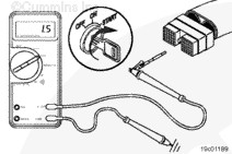
Remove the lead from engine brake selector signal number 1 and insert it into engine brake selector signal number 2 of the OEM harness connector.
Move the engine brake ON/OFF switch to the ON position. Move the engine brake level switch to position number 2 for a six-position switch or to position number 1 for a three-position switch.
The multimeter
must show a closed circuit (10 ohms or less). If the circuit is
not closed, inspect engine brake selector signal number 2 wire for an open circuit, provided that the switch has been previously checked. Refer to the OEM troubleshooting and repair manual for repair procedures.
If the resistance is within the specification, engine brake selector signal number 2 wire
must be checked for a short circuit to ground, a short circuit from pin to pin, and a short circuit to an external voltage source.
Remove the lead from engine brake selector signal number 2 and insert it into engine brake selector signal number 3 of the OEM harness.
Move the engine brake ON/OFF switch to the ON position. Move engine brake level switch to position number 3.
The multimeter
must show a closed circuit (10 ohms or less). If the circuit is
not closed, inspect the engine brake selector signal number 3 wire for an open circuit, provided that the switch has been previously checked. Refer to the OEM troubleshooting and repair manual for repair procedures.
If the resistance is within the specification, the engine brake selector signal number 3 wire
must be checked for a short circuit to ground, a short circuit from pin to pin, and a short circuit to an external voltage source.
Connect all components after completing the repair.
|
 CAUTION


;)
;)
;)
;)
;)
;)
;)
;)
;)
;)
;)
;)
;)
;)