This procedure is designed to troubleshoot electrical circuit faults that are intermittent and are currently inactive. This procedure can also be used to troubleshoot high inactive counts of circuit related fault codes.
If multiple fault codes are present, use a wiring diagram to check for common sensor supplies and ground circuits that may be shared between sensors, actuators, and switches. Pressure sensors may share a common 5 volt supply and ground circuit. Temperature sensors and actuators may share a common ground circuit. If either a sensor supply or a ground circuit has an intermittent connection, fault codes related to all the sensors may be active or have high counts of inactive fault codes.
If the conditions for a fault code to trigger exist and then the conditions are no longer present, an inactive fault code is created. When conditions are intermittent, there may be multiple inactive counts for a given fault code. If there are more than 10 inactive counts, the fault code should be troubleshot as an active fault code. Troubleshooting priority should be given to fault codes that are associated engine performance components such as the turbocharger, EGR valve, or any system related fault code.
Interview the operator and determine the engine operating conditions when the fault occurs and what symptoms occur when the fault is active.
Determine if there have been any recent service repairs or maintenance performed that may be related to the intermittent condition.
Review the “Shop Talk” section of the fault code troubleshooting tree. Shop Talk will give additional troubleshooting information and will list possible causes for the fault code.
Verify the electronic control module (ECM) calibration is correct. Check the calibration revision history found on QuickServe® Online for applicable fixes to the calibration stored in the ECM. If necessary, recalibrate the ECM. 019-032 (ECM Calibration Code) in Section 19 in the corresponding Troubleshooting and Repair Manual for the engine being serviced.
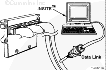
Connect INSITE™ and open the Data Monitor/Logger feature. Monitor the sensor signal voltage for the appropriate sensor. Also monitor the actual value of the sensor or component.
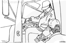
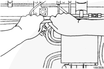
Beginning at the component in question and working back through the harness to the ECM, gently twist, bend and pull at each connection and in between connections in the harness.
While performing the Harness Shake Test, the sensor signal voltage that INSITE™ displays should remain between steady. A typical reading should be between 0.5 and 5.12 volts.
NOTE: This procedure can also be used to check for loose or damaged wires for switches. Switch status can be monitored with INSITE™. Look for switch changes when performing the Harness Shake Test.
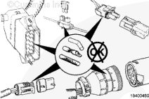
If the fault code goes active, if inactive counts increase, the sensor signal voltage fluctuates, or the switch status changes, there is a loose connection or damaged wire at that specific location. Refer to Procedure 019-361, Component Connector and Pin Inspection, and inspect the pins at the connectors in question. Repair or replace as necessary.
NOTE: The ECM will not change the status of switches and faults instantaneously. Approximately 10 to 15 seconds should be used to gently twist the harness and see a reading change from the ECM. Trying to monitor too many parameters at one time with INSITE™ will slow down the update rate on the screen. Keep the number of parameters monitored with INSITE™ to minimum to increase the update rate.
With the engine running, connect to INSITE™ and open up the Data Monitor/Logger feature. Monitor the sensor signal voltage for the appropriate sensor. Also monitor the actual value of the sensor or component.
While performing the Harness Shake Test, the sensor signal voltage that INSITE™ displays should remain between steady. A typical reading should be between 0.5 and 5.12 volts.
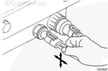
Now gently bend, twist, and pull the connections and in between connections in the harness while monitoring the sensor signal voltage.
If the sensor signal voltage fluctuates during the test, then there is a loose connection or damaged wire at that specific location. Inspect the pins at the connectors in question.
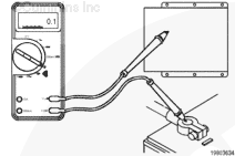
Check for poor battery and chassis grounds. Firmly pull on ground wires or cables checking for loose connections. Check the following grounds making sure they are secure, clean, and on a non-painted surface:
engine block grounds
chassis (or frame rail) grounds
ECM grounds
alternator and starter negative posts
While performing this step, check to see if the fault code goes active, or if inactive counts increase. If this happens, there is a loose connection or damaged wire at that location. Disconnect, clean grounding cables and grounding surfaces, then reconnect. Repair or replace grounding cables or wires if necessary.
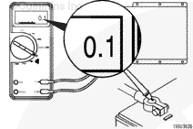
All resistance values should measure less than 1 ohm. If resistance values exceed 1 ohm, clean grounding cables and grounding surfaces, then reconnect. Repair or replace grounding cables or wires if necessary.
This test must be performed with the actuator connected to the wiring harness.
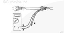
With the sensor or actuator disconnected from the wiring harness, measure the voltage at the engine harness connector of the component.
Connect the sensor or actuator to the wiring harness and measure the voltage with all the components connected. Use a breakout cable or back-probe the connector with the multimeter leads when performing this check.
The voltage to the component should be within 0.5 volts of the original voltage measured. If the voltage drops more than 0.5 volts, check for intermittent connections, cut wires, or corroded relay connections between the actuator and the ECM.
When a sensor circuit is shorted high or shorted low, the sensor value will be locked to a default value when the fault code is active. The default value will usually be set to a value that is within the standard operating range of the sensor. When monitoring the sensor values with a service tool it will appear as if the sensor is reading a correct value even when the fault code is active. Some typical global default sensor values are as follows:
Engine Coolant Temperature = 104.4°C [219.9°F]
Intake Manifold Temperature = 21.3°C [70.3°F]
Intake Manifold Pressure = 2.4 kpa [0.7 inHg]
EGR Temperature = 37.8°C [100°F]
Engine Oil Pressure = 73.1 kPa [10.6 psi]
Be aware when troubleshooting intermittent circuit fault codes that the value displayed with a service tool could be a default sensor reading. Always use the sensor signal voltage measurement when troubleshooting intermittent circuit fault codes.
If further investigation is necessary, use the Data Monitor/Logger feature in INSITE™ to monitor the inputs and outputs of a running engine and to capture data to a log file. The Logger feature in INSITE™ will allow for information to be captured during the intermittent event and can reviewed at a later time.
Hello, I'm Jack, a diesel engine fan and a blogger. I write about how to fix and improve diesel engines, from cars to trucks to generators. I also review the newest models and innovations in the diesel market. If you are interested in learning more about diesel engines, check out my blog and leave your feedback.
View all posts by Jack


;)
;)
;)
;)
;)
;)
;)
;)
;)
;)
;)
;)
;)
;)
;)
;)
;)
;)
;)
;)