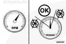
Operate the engine at high idle and record the fuel pressure at the inlet and outlet of the fuel filter. Subtract the outlet reading from the inlet reading to determine the restriction.
Maximum Allowable Pressure Drop Across Fuel Filter
kpa
psi
80
MAX
11.7
If the pressure drop is greater than the specified value, the fuel filter must be replaced.
Remove the Compuchek™ fittings and install the threaded plugs into the diagnostic ports. See Section 17 for the correct torque value.
Depending on the circumstance, diesel fuel is flammable. When inspecting or performing service or repairs on the fuel system, to reduce the possibility of fire and resulting severe personal injury, death, or property damage, never smoke or allow sparks or flames (such as pilot lights, electrical switches, or welding equipment) in the work area.
Close the fuel supply and return valves, if equipped.
Disconnect the wiring harness from the water-in-fuel sensor, if equipped.
Disconnect the wiring harness from the fuel heater, if equipped.
Loosen and remove the fuel filter.
Make sure the seal ring does not stick to the filter head.
Remove the ring with an o-ring pick, if necessary.
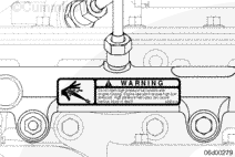
Do not open the high-pressure fuel system with the engine running. Engine operation causes high fuel pressure. High-pressure fuel spray can cause serious injury or death.
Open the fuel supply and return valves, if equipped.
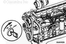
Cycle the keyswitch and allow the lift pump to operate for 30 seconds. Then turn the keyswitch OFF and back ON again, allowing the lift pump to operate again.
Allow the lift pump to operate for three or four 30-second cycles before attempting to start the engine.
Operate the fuel lift pump to help prime the fuel system. Turn the keyswitch to RUN, but do not attempt to start the engine. This will cause the ECM to operate the fuel lift pump through a priming cycle which lasts at least 30 seconds. Cycle the lift pump several times by keying OFF, waiting 10 seconds, and keying ON again.
Once the engine is started, slowly increase the engine speed while air is purged from the fuel plumbing.
Hello, I'm Jack, a diesel engine fan and a blogger. I write about how to fix and improve diesel engines, from cars to trucks to generators. I also review the newest models and innovations in the diesel market. If you are interested in learning more about diesel engines, check out my blog and leave your feedback.
View all posts by Jack


 WARNING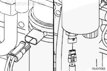
 CAUTION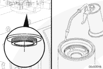

;)
;)
;)
;)
;)
;)
;)
;)
;)
;)
;)
;)
;)
;)