ISC, ISCe, QSC8.3, ISL, ISLe3, ISLe4 and QSL9 Engines – 014-005   Engine Testing (Engine Dynamometer)

Table of Contents

Setup

Setup

TOC

Use engine lifting fixture, Part Number 3162871, to install the engine to the test stand. Align and connect the dynamometer. Refer to the manufacturer’s instructions for aligning and testing the engine.

NOTE: Make sure the dynamometer capacity is sufficient to permit testing at 100 percent of the engines rated horsepower. If the capacity is not enough, the testing procedure must be modified to the restrictions of the dynamometer.

SMALL | MEDIUM | LARGE


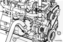
Connect the coolant supply to the water inlet connection (1).

Connect the coolant return to the water outlet connection (2).

Install the drain plugs, close all the water drain cocks, and make sure all the clamps and fittings are tight.

SMALL | MEDIUM | LARGE


Fill the cooling system with coolant to the bottom of the fill neck in the radiator fill (or expansion) tank.

 
SMALL | MEDIUM | LARGE


Inspect the engine for coolant leaks at connections, fittings, plates, and plugs. Repair if necessary.

SMALL | MEDIUM | LARGE


Air Inlet Restriction

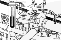
Connect a water manometer, Part Number ST-1111-3, to the turbocharger air inlet pipe to test air restriction.

NOTE: The manometer connection must be installed at a 90-degree angle to the airflow in a straight section of pipe, one pipe diameter before the turbocharger.

NOTE: A vacuum gauge, Part Number ST-434, can be used in place of the water manometer.

Measurements
  mm-h2o in-h2o
Minimum Gauge Capacity 760 30

SMALL | MEDIUM | LARGE


Exhaust Restriction

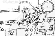
Connect a mercury manometer to a straight section of the exhaust piping near the turbocharger outlet to check exhaust restriction.

NOTE: A pressure gauge, Cummins Part Number ST-1273, can be used in place of the mercury manometer.

NOTE: For automotive applications, a tapped hole is provided on the inlet side of the catalyst for checking exhaust restrictions.

Measurements
  mm-hg in-hg
Minimum Gauge Capacity 254 10

SMALL | MEDIUM | LARGE


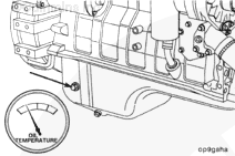
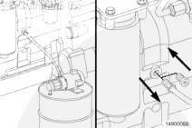
Attach the lubricating oil temperature sensor in the location shown.

Measurements
  celsius fahrenheit
Minimum Gauge Capacity 150 300

SMALL | MEDIUM | LARGE


 CAUTION 

The lubricating oil system must be primed before operating the engine after if has been rebuilt to avoid internal damage.

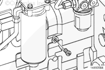
To prime the lubricating oil system using external pressure, connect the supply to a tapped hole in the main lubricating oil rifle.

SMALL | MEDIUM | LARGE


Use a pump capable of supplying 210 kPa [30 psi] of continuous pressure. Connect the pump to the port on the main lubricating oil rifle as shown.

Use clean lubricating oil to prime the system until the oil pressure registers on the gauge.

Remove the lubricating oil supply tube and install the plug.

SMALL | MEDIUM | LARGE


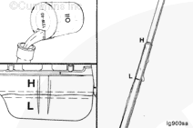
Make sure the lubricating oil has had time to drain to the lubricating oil pan and fill the engine to the high mark as measured on the dipstick.

Use the correct lubricating oil as specified in the Operation and Maintenance Manual.

SMALL | MEDIUM | LARGE


If an external pressure pump is not available, prime the lubricating system according to the following procedure.

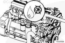
Fill the engine with lubricating oil to the high-level mark on the dipstick.

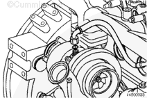
Disconnect the turbocharger lubricating oil supply tube.

Pour 50 to 60 cc [2.0 to 3.0 fl oz] of clean 15W-40 lubricating oil into the turbocharger lubricating oil supply hole.

Connect the lubricating oil supply tube to the turbocharger.

SMALL | MEDIUM | LARGE


 CAUTION 

Mechanical overtightening can distort the threads or damage the filter element seal.

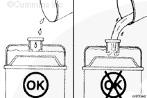
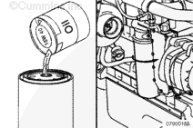
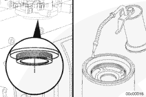
Fill the lubricating oil filters with clean 15W-40 lubricating oil.

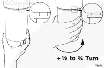
Screw the filters onto the filter head fitting until the gasket contacts the filter head surface.

Tighten the filter as specified by the manufacturer.

SMALL | MEDIUM | LARGE


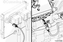
CM850 Control Module – Disconnect the 4-pin power connector from the ECM to prevent the engine from starting.

CM554 Control Module -Disconnect the CAPS injection control valve connector so that the engine does not start.

SMALL | MEDIUM | LARGE


 CAUTION 

Do not crank the starting motor for periods longer than 30 seconds. Excessive heat will damage the starting motor.

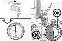
Crank the engine until the lubricating oil pressure gauge indicates system pressure.

NOTE: Allow two minutes between the 30-second cranking periods so the starter motor can cool.

NOTE: If pressure is not indicated, find and correct the problem before continuing.

SMALL | MEDIUM | LARGE


CM850 Control Module – Connect the 4-pin power connector to the ECM.

CM554 Control Module – Connect the injection control valve connector.

SMALL | MEDIUM | LARGE


Allow the lubricating oil to drain into the lubricating oil pan and measure the lubricating oil level with the dipstick.

Add lubricating oil as necessary to bring the level to the high-level mark.

SMALL | MEDIUM | LARGE


Lubricate the gasket on the oil filter with clean 15W-40 lubricating oil.

SMALL | MEDIUM | LARGE


Screw the oil filter onto the filter head until the gasket contacts the filter head surface.

Tighten the filter as specified by the manufacturer.

SMALL | MEDIUM | LARGE


 CAUTION 

Do not attempt to install pipe thread fittings in plastic or rubber intake piping.

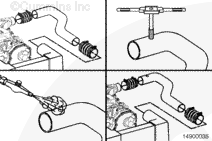
If INSITE™ electronic service tool is available, use it to monitor intake manifold pressure during the test. This eliminates the need to install a gauge as shown below.

If the air crossover tube does not have a pipe plug and tapped hole, perform the following procedure:

  • Remove the charge air cooler air crossover tube from the engine.
  • Drill and tap a 1/8-inch pipe thread hole in the tube four to six inches from intake opening.
  • Clean all metal shavings from the air crossover tube.
  • Install the crossover tube.

SMALL | MEDIUM | LARGE


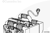
To determine the amount of turbocharger boost, remove the pipe plug in the air crossover tube and install the intake manifold pressure sensor or pressure gauge, Part Number ST-1273.

Measurements
  mm-hg in-hg
Minimum Gauge Capacity 1905 75

For an accurate engine crankcase blowby measurement, insert a blowby checking tool in the crankcase breather vent.

Connect a water manometer to the blowby tool. A pressure gauge can be used in place of the manometer.

Measurements
  mm-h2o in-h2o
Minimum Gauge Capacity 1270 50

SMALL | MEDIUM | LARGE


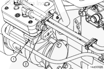
To be able to unload the compressor, connect a source of compressed air to the unloader (1). This air line must contain a valve between the source and the unloader.

NOTE: All air compressors manufactured by Cummins Inc. must be loaded during engine run-in. All air compressors must be unloaded during the engine performance check.

NOTE: The compressed air load in the accompanying illustration must be attached to the air compressor outlet (2).

SMALL | MEDIUM | LARGE


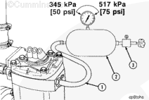
To provide a load on the air compressor, connect an air tank (2) to the compressor outlet, use steel tubing or a high-temperature hose (1).

Install an air regulator (3) that can maintain tank air pressure of 345 to 517 kPa [50 to 75 psi] at both the minimum and the maximum engine rpm.

Measurements
  celsius fahrenheit
Hose Temperature (Minimum) 260 500

NOTE: If the engine is equipped with a variable geometry turbocharger, the turbocharger control valve will require a continous air supply of at least 621 kPa [90 psi].

SMALL | MEDIUM | LARGE


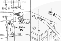
Inspect the voltage rating on the starter motor before installing the electrical wiring.

Attach electrical wires to the starter motor and the batteries, if used.

NOTE: If another method of starting the engine is used, follow the manufacturer’s instructions to make the necessary connections.

SMALL | MEDIUM | LARGE
Last Modified:  06-Jul-2005