 |
|
SAE J1939 Multiplexed Accelerator Pedal or Lever Sensor System – Received Network Data In Error
|

Overview
| CODE | REASON | EFFECT |
| Fault Code: 287 PID: P91 SPN: 91 FMI: 2/19 LAMP: Red SRT: |
SAE J1939 Multiplexed Accelerator Pedal or Lever Sensor System – Received Network Data In Error. The OEM vehicle electronic control unit (VECU) detected a fault with its accelerator pedal. |
Engine may only idle or engine will not accelerate to full speed. |
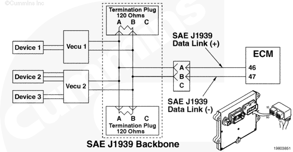 ISX and ISM – SAE J1939 Multiplexed Accelerator Pedal or Lever Sensor System
|
;)
;)
Circuit Description
Normally, switches, accelerators, and other components are connected to the engine electronic control module (ECM) directly through individual wires. Multiplexing allows those same components to be hard wired to an original equipment manufacturer (OEM) VECU or transmission electronic control unit in the cab. Then component values and states from components (such as sensors, accelerators, and switches) can be transmitted from the OEM VECU to the Cummins engine ECM over the SAE J1939 datalink.
Messages sent from the OEM VECU or transmission electronic control unit are received by the Cummins engine ECM and used for controlling the engine. The Cummins ECM and OEM VECU must be configured properly so that proper operation of the multiplexed components will occur.
Component Location
The engine ECM is located on the intake side of the engine. Refer to Procedure 100-002 (Engine Diagrams) in Section E for a detailed component location view. The J1939 datalink wiring and VECU location varies by OEM.
Conditions for Running the Diagnostics
This diagnostic runs continuously when the keyswitch is in the ON position.
Conditions for Setting the Fault Codes
The accelerator is depressed and the OEM VECU reads accelerator position as greater than 0%, but the secondary throttle position sensor indicates it is in the idle position.
When the accelerator is released and the OEM VECU reads accelerator position as 0%, but the secondary throttle position sensor indicates it is not in the idle position.
The OEM VECU determines that the accelerator signal wire is shorted high or shorted low.
Action Taken When the Fault Code is Active
- The ECM illuminates the amber CHECK ENGINE light immediately when the diagnostic runs and fails.
- The multiplexed device will not operate.
Conditions for Clearing the Fault Code
The ECM will turn off the amber CHECK ENGINE light immediately after the diagnostic runs and passes.
Shop Talk
Verify the electronic control module (ECM) calibration is correct. Check the calibration revision history found on QuickServe® Online for applicable fixes to the calibration stored in the ECM. If necessary, recalibrate the ECM. Refer to Procedure 019-032 (ECM Calibration Code) in Section 19 in the corresponding Troubleshooting and Repair Manual for the engine being serviced.
This fault can occur when the OEM VECU detects an error on the accelerator. The ECM has been set up properly (components enabled and OEM VECU source addressed correctly) to receive multiplexed information for the idle validation switch states and accelerator position over the J1939 datalink from an OEM VECU, and the OEM VECU is transmitting the message for that component.
The three types of errors that can occur for this fault are:
- When the accelerator is depressed and the OEM VECU reads accelerator position as greater than 0%, but the idle validation switch indicates it is in the idle position. This fault status is transmitted to the Cummins ECM on the J1939 datalink, which causes this fault to occur in the Cummins ECM.
- When the accelerator is released and the OEM VECU reads accelerator position as 0%, but the idle validation switch indicates it is not in the idle position. This fault status is transmitted to the Cummins ECM on the J1939 datalink, which causes this fault to occur in the Cummins ECM.
- The OEM VECU determines that the accelerator signal line is shorted high or shorted low.
NOTE: It is still possible to get a Fault Code 285 or 286 if there is an incorrect setup in the OEM VECU or Cummins ECM, for other components, or the accelerator and idle validation switch, or if the datalink is damaged. The OEM configurations must multiplex the accelerator and idle validation switch inputs together to allow the use of the J1939 multiplexing and limp home feature for these components. The INSITE™ electronic service tool can be used to monitor multiplexed components.
Refer to Troubleshooting Fault Code t05-287