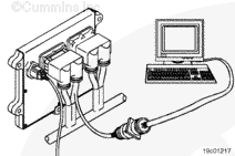
Connect an electronic service tool to the vehicle datalink.
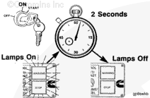
Turn the keyswitch to the ON position.
Select the monitor mode on the electronic service tool. The electronic service tool must be able to communicate with the ECM. If the ECM will not communicate with the service tool, see the Communication Error – Electronic Service Tool or Control Device symptom tree.
Record the values of ECM Distance Offset, ECM Time Offset, Engine Distance Offset, and Engine Time Offset prior to replacement or calibration of the ECM. These parameters can be found in the Trip Information section of Features and Parameters.
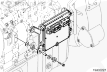
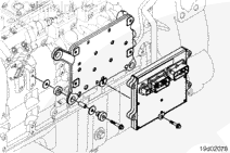
The ECM location varies by engine type. See the engine diagram for ECM mounting location.
NOTE: Record all programmable parameters, features, and calibration information from the old ECM before disconnecting the harness connectors. This information will be needed to program the new ECM.
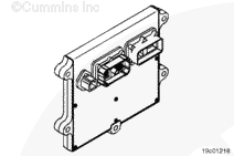
Disconnect the ECM power harness, engine harness, and OEM harness connectors from the ECM, if they are not already disconnected.
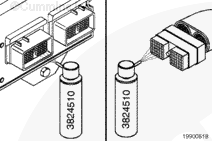
Do not blow compressed air into the ECM ports or connectors. Compressed air can contain moisture due to condensation.
Use quick-dry electrical contact cleaner, Part Number 3824510, to remove all dirt and moisture from the ECM connector ports and the harness connectors.
Connect the ECM power harness, engine harness, and OEM harness connectors to the ECM. Tighten the connector capscrews to the ECM connectors.
Adjust the values of ECM Distance Offset, ECM Time Offset, Engine Distance Offset, and Engine Time Offset after calibrating the ECM. These parameters can be found in the Trip Information section of Features and Parameters.
Hello, I'm Jack, a diesel engine fan and a blogger. I write about how to fix and improve diesel engines, from cars to trucks to generators. I also review the newest models and innovations in the diesel market. If you are interested in learning more about diesel engines, check out my blog and leave your feedback.
View all posts by Jack


 CAUTION

;)
;)
;)
;)
;)
;)
;)
;)
;)
;)
;)
;)