The engine protection override switch is an original equipment manufacturer (OEM) installed switch that allows a driver to abort a pending engine protection shutdown. The switch is only active when it is properly wired by the OEM and the engine protection shutdown override feature is enabled in the calibration. If the switch is not preventing a shutdown from occurring, check the feature with the electronic service tool to see if it is enabled in the calibration.
If INSITE™ electronic service tool is available, monitor the engine protection override switch for proper operation. If not, follow the troubleshooting procedures in this section.
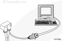
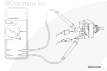
Locate the engine protection override switch. Label the wires with the location on the switch or the wire number. Remove the electrical connectors from the switch. Adjust the multimeter to measure resistance. Touch one multimeter probe to one of the terminals on the switch. Touch the other multimeter probe to the other terminal of the switch.
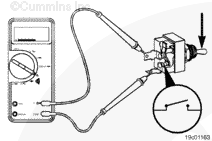
Place the switch in the non-override (released) position and measure the resistance. The multimeter must show an open circuit (100k ohms or more). If the circuit is not open, the switch is defective. Refer to the original equipment manufacturer (OEM) troubleshooting and repair manual for replacement procedures.
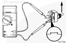
Place the switch in the override (pressed) position and measure the resistance. The multimeter must show a closed circuit (10 ohms or less). If the circuit is not closed, the switch is defective. Refer to the OEM troubleshooting and repair manual for replacement procedures. If the resistance value is correct, the switch must still be checked for a short circuit to ground.
Touch one of the multimeter probes to one of the switch terminals. Touch the other probe to chassis ground. Move the switch to the non-override (released) position and measure the resistance. The multimeter must show an open circuit (100k ohms or more).
If the circuit is not open, the switch has failed. Refer to the OEM troubleshooting and repair manual for replacement procedures.
If the switch passes all of the previous checks, the circuit must be checked for an open circuit, a short circuit to ground, a short circuit from pin-to-pin, and a short circuit to an external voltage source.
Hello, I'm Jack, a diesel engine fan and a blogger. I write about how to fix and improve diesel engines, from cars to trucks to generators. I also review the newest models and innovations in the diesel market. If you are interested in learning more about diesel engines, check out my blog and leave your feedback.
View all posts by Jack


;)
;)
;)
;)
;)
;)
;)
;)
;)
;)