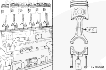
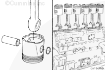
NOTE: The piston and connecting rod assemblies must be installed in the same cylinder number from which they were removed, to make sure there is a correct fit of worn mating surfaces if parts are used again.
Use a tag to mark the cylinder number from which each piston and rod assembly was removed.
When using solvents, acids, or alkaline materials for cleaning, follow the manufacturer’s recommendations for use. Wear goggles and protective clothing to reduce the possibility of personal injury.
WARNING
Some solvents are flammable and toxic. Read the manufacturer’s instructions before using.
WARNING
When using a steam cleaner, wear safety glasses or a face shield, as well as protective clothing. Hot steam can cause serious personal injury.
WARNING
Wear appropriate eye and face protection when using compressed air. Flying debris and dirt can cause personal injury.
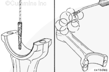
Use a nylon bristle brush to clean the oil drillings.
Steam clean or use solvent to clean the connecting rods.
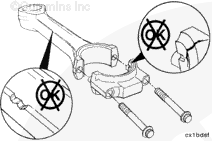
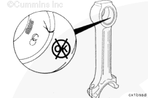
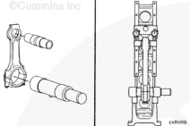
Inspect the rod pin bore bushing for damage or misalignment of the oil passage and the bushing.
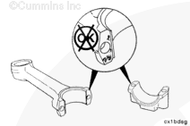
Replace any piston pin bushing that has evidence of scoring, galling, or scuffing. Replace any bushing that has turned.
Special tools and precision machining are required to replace bushings. If Cummins® approved tools and procedures are not available, the connecting rod must be replaced.
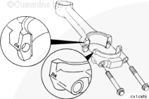
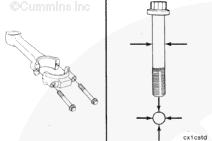
The rod cap alpha characters must match the alpha characters on the connecting rod and must be installed with the characters aligned to prevent damage to the connecting rods and crankshaft.
If any of the measurements are not within the specifications, the rod must be repaired or replaced.
The bushing must be precision machined after installation. If machining capability is available, the bushing can be replaced. Refer to the Alternative Repair Manual, Bulletin 3379035.
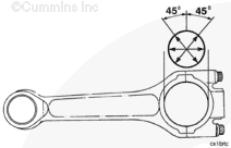
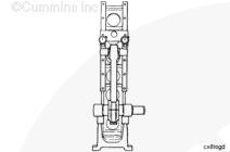
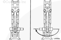
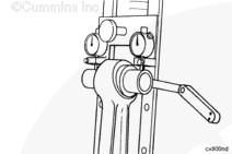
Use a connecting rod checking fixture, Part Number ST-561, and a connecting rod mandrel set, Part Number 3823785, to inspect the bend and twist of the rods.
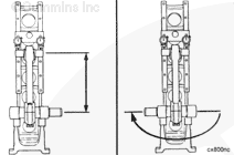
Calibrate the checking fixture with a new rod that has been measured for correct center to center length, 304.75 mm to 304.80 mm [11.998 in to 12.000 in].
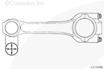
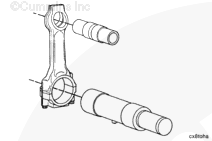
Install the piston pin mandrel from the connecting rod mandrel set, Part Number 3823785, into the piston pin bore.
NOTE: Use a mandrel, Part Number 3823787, if the piston pin bushing has been removed or the mandrel, Part Number 3823788, if the bushing is still in place.
Install the mandrel, Part Number 3823785, into the crankshaft bore and expand the mandrel.
NOTE: Make sure the pin on the mandrel is pointed down and locked in position in the center of the connecting rod.
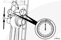
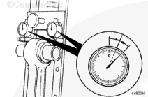
Check the dial indicators for the “0” position again.
If the dial indicators show any change from “0”, adjust the dials to half the indicated reading.
The fixture is now calibrated to allow the connecting rod to be installed into the fixture in either direction, and the dials will indicate an equal deflection on either side of “0”.
NOTE: The piston and connecting rod assemblies must be installed in the same cylinder number from which they were removed, to make sure there is a correct fit of worn mating surfaces if parts are used again.
Hello, I'm Jack, a diesel engine fan and a blogger. I write about how to fix and improve diesel engines, from cars to trucks to generators. I also review the newest models and innovations in the diesel market. If you are interested in learning more about diesel engines, check out my blog and leave your feedback.
View all posts by Jack


 WARNING

 CAUTION


;)
;)
;)
;)
;)
;)
;)
;)
;)
;)
;)
;)
;)
;)
;)
;)
;)
;)
;)
;)
;)
;)
;)
;)
;)
;)
;)
;)
;)
;)
;)
;)
;)
;)
;)
;)