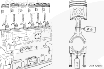
must
be installed in the same cylinder number from which they were removed to make sure there is a correct fit of worn mating surfaces if parts are used again.
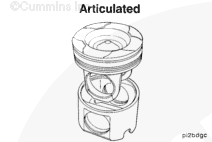
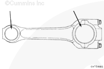
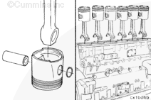
Use a tag to mark the cylinder number from which each piston and rod assembly was removed.
When using solvents, acids, or alkaline materials for cleaning, follow the manufacturer’s recommendations for use. Wear goggles and protective clothing to reduce the possibility of personal injury.
CAUTION
To avoid damage to the piston crown, the cleaning solvent must be approved for bushing material.
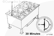
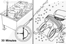
Allow the pistons to soak for a minimum of 30 minutes in a tank containing an approved cleaning solvent for aluminum.
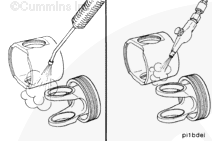
Use a hot, soapy solution and a non-metallic brush to remove carbon deposits.
NOTE: A plastic bead, Part Number 3822735, is available which can be used to clean pistons, including aluminum ring grooves. Do not
bead blast pin bores.
CAUTION
Do not use a metal brush. A metal brush will damage the piston ring grooves. Do not use glass beads to clean the grooves. Walnut shell blasting can be used on grooves with a ni-resist insert and on the dome or crown of the piston. Use the minimum effective pressure and do not concentrate the spray in one area for an extended period of time. Do not use glass beads or walnut shell blasting on the aluminum grooves or pin bores. This can damage the pin bore surface finish or prevent the rings from seating correctly in the ring grooves.
not
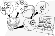
use the crown or skirt if cracks or scuff marks are found. Scratches in the skirt are
not
acceptable if they are visually
not
acceptable.
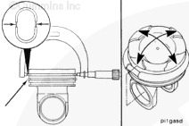
Use crack detection kit, Part Number 3375432 or equivalent, to check for cracks on the piston crown and in and around the piston pin bore. Do not
use if cracked or scuffed. If the crown is
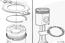
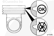
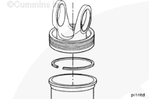
Visually inspect the piston ring lands and ring grooves for wear. A worn groove will have a detectable step at the back of the groove and a rolled edge at the surface of the piston or the ring groove outside diameter. Pistons exhibiting this wear are
not
acceptable for reuse.
Reference the Parts Reuse Guidelines, Bulletin 3810303.
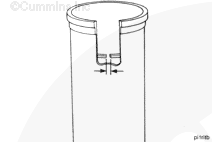
Use piston ring groove wear gauges, Part Numbers 3823870 and 3823869, and a 5 to 6-inch micrometer to inspect the top and second grooves (compression rings).
NOTE: The piston
must
be replaced if measured dimensions are less than those in the table below.
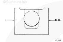
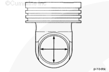
Measure each ring groove (diameter over pins) when the piston temperature is at 21°C [70°F] in two places 90 degrees apart as shown.
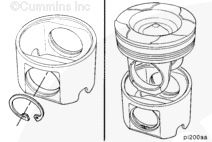
Visually inspect the piston pin for scratches, grooves, or other damage. Do
not
reuse if it is visually
not
acceptable.
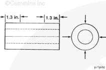
Measure the piston pin outside diameter at both ends as shown in two places 90 degrees apart.
Piston Pin Outside Diameter
mm
in
63.4928
MIN
2.49972
63.4997
MAX
2.4999
NOTE: Discard the piston pin if it is more than 0.03 mm [0.001 in] out of round. If piston pin measurements exceed those in the table, do not
reuse. If the piston pin is
not
acceptable for reuse, do
not
use the matching piston. Cummins Inc, recommends replacing pistons and pins in sets.
Hello, I'm Jack, a diesel engine fan and a blogger. I write about how to fix and improve diesel engines, from cars to trucks to generators. I also review the newest models and innovations in the diesel market. If you are interested in learning more about diesel engines, check out my blog and leave your feedback.
View all posts by Jack


 WARNING
  CAUTION


;)
;)
;)
;)
;)
;)
;)
;)
;)
;)
;)
;)
;)
;)
;)
;)
;)
;)
;)
;)
;)
;)
;)
;)
;)
;)
;)
;)
;)
;)
;)
;)
;)
;)