Batteries can emit explosive gases. To reduce the possibility of personal injury, always ventilate the compartment before servicing the batteries. To reduce the possibility of arcing, remove the negative (-) battery cable first and attach the negative (-) battery cable last.
CAUTION
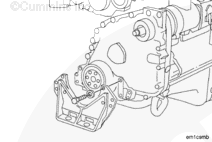
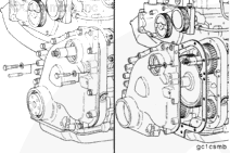
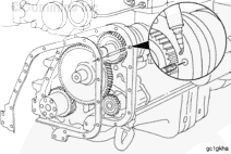
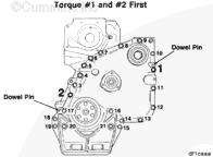
If the accessory drive dowel pin has been installed in the accessory drive shaft, the dowel pin must be removed before attempting to remove the gear cover to prevent damage to the accessory drive bushing.
Disconnect the batteries. Refer to the OEM service manual.
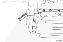
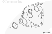
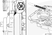
Use extreme care when releasing the oil pan gasket from the gear cover to prevent damage to the gasket. If the gasket is damaged, the oil pan must be removed and the gasket replaced. Refer to Procedure 007-025 in Section 7.
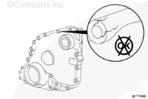
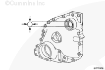
Insert a feeler gauge or a shim stock between the gear cover and the oil pan gasket. Move the feeler gauge or the shim stock back and forth to release the gasket from the gear cover.
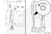
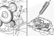
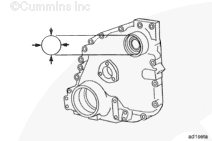
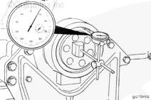
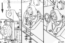
Mount a dial indicator on the front face of the crankshaft. Place the indicator plunger against the oil seal bore, and set the dial indicator at “0” (zero).
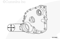
Rotate the crankshaft one complete revolution while monitoring the indicator. Use the accessory drive nut to bar the engine over. The total indicator reading
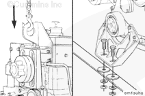
Lower the engine to the crossmember. Install and tighten the capscrews which hold the front engine support to the crossmember. Refer to the OEM service manual for torque specifications.
Batteries can emit explosive gases. To reduce the possibility of personal injury, always ventilate the compartment before servicing the batteries. To reduce the possibility of arcing, remove the negative (-) battery cable first and attach the negative (-) battery cable last.
CAUTION
If the accessory drive dowel pin has been installed in the accessory drive shaft, the dowel pin must be removed before attempting to remove the gear cover to prevent damage to the accessory drive bushing.
Hello, I'm Jack, a diesel engine fan and a blogger. I write about how to fix and improve diesel engines, from cars to trucks to generators. I also review the newest models and innovations in the diesel market. If you are interested in learning more about diesel engines, check out my blog and leave your feedback.
View all posts by Jack

 WARNING
  CAUTION


;)
;)
;)
;)
;)
;)
;)
;)
;)
;)
;)
;)
;)
;)
;)
;)
;)
;)
;)
;)
;)
;)
;)
;)
;)
;)
;)
;)
;)
;)
;)
;)
;)
;)
;)
;)