To reduce the possibility of personal injury, avoid direct contact of hot oil with your skin.
WARNING
Some state and federal agencies have determined that used engine oil can be carcinogenic and cause reproductive toxicity. Avoid inhalation of vapors, ingestion, and prolonged contact with used engine oil. If not reused, dispose of in accordance with local environmental regulations.
WARNING
Batteries can emit explosive gases. To reduce the possibility of personal injury, always ventilate the compartment before servicing the batteries. To reduce the possibility of arcing, remove the negative (-) battery cable first and attach the negative (-) battery cable last.
Disconnect the batteries. Refer to the OEM service manual.
When using solvents, acids, or alkaline materials for cleaning, follow the manufacturer’s recommendations for use. Wear goggles and protective clothing to reduce the possibility of personal injury.
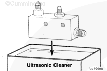
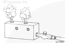
Use ultrasonic cleaners, Part Number 3376665 or 3375001, and ultrasonic cleaners solution, Part Number 33750003, to clean the viscosity sensor.
When using solvents, acids, or alkaline materials for cleaning, follow the manufacturer’s recommendations for use. Wear goggles and protective clothing to reduce the possibility of personal injury.
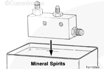
Use mineral spirits to neutralize the solution after cleaning.
To reduce the possibility of personal injury, avoid direct contact of hot oil with your skin.
WARNING
Some state and federal agencies have determined that used engine oil can be carcinogenic and cause reproductive toxicity. Avoid inhalation of vapors, ingestion, and prolonged contact with used engine oil. If not reused, dispose of in accordance with local environmental regulations.
WARNING
Batteries can emit explosive gases. To reduce the possibility of personal injury, always ventilate the compartment before servicing the batteries. To reduce the possibility of arcing, remove the negative (-) battery cable first and attach the negative (-) battery cable last.
Operate the engine until the water temperature reaches 82°C [180°F], and check for leaks.
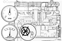
The viscosity sensor controls the oil pressure signal to the lubricating pump pressure regulator. It allows high oil rifle pressure with cold, thick oil, but normal oil rifle pressure with warm oil. The high oil pressure with cold viscous oil highly improves oil fill of the STC injector tappets. This provides maximum engine timing advancement and white smoke control. The sensor allows normal oil pressure when the oil is warm.
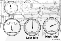
Effect of Viscosity Sensor on Main Oil Rifle Pressure
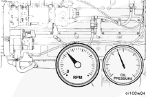
Operate the engine until the oil temperature stabilizes. Observe the oil rifle pressure as the temperature of the oil is increasing. Compare results with the values given in the Effect of Viscosity Sensor on Main Oil Rifle Pressure table.
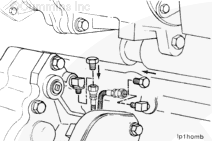
If the results do not agree with the Effect of Viscosity Sensor on Main Oil Rifle Pressure table, verify that the base engine lubricating system is operating properly before removing the viscosity sensor.
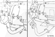
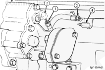
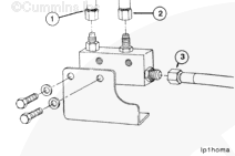
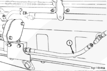
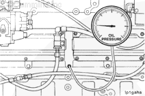
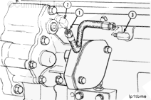
Connect a pressure signal line from the oil rifle to the lubricating pump construct a flexible hose (1) of 305 mm [12.0 in] to connect the main oil rifle (3) to the lubricating oil pump (2).
Hello, I'm Jack, a diesel engine fan and a blogger. I write about how to fix and improve diesel engines, from cars to trucks to generators. I also review the newest models and innovations in the diesel market. If you are interested in learning more about diesel engines, check out my blog and leave your feedback.
View all posts by Jack

 WARNING


;)
;)
;)
;)
;)
;)
;)
;)
;)
;)
;)
;)
;)
;)
;)
;)
;)
;)
;)
;)
;)
;)
;)
;)
;)
;)
;)
;)
;)
;)
;)
;)
;)
;)
;)
;)