Important: The engine block surfaces must be clean.
Do not use a sealer on the cylinder head gaskets.
The cylinder head gaskets are manufactured with the proper amount of sealant “Printed” on its surface.
Additional sealer may cause leakage or a malfunction.
In addition, some sealers may attack the sealant already on the cylinder head gasket.
Important: The cylinder head gasket material is soft. Handle the cylinder head gasket with care and make sure that the sealing surfaces are not damaged.
1. Assemble the cylinder head. Refer to Cylinder Head Assemble.
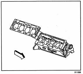
2. Install the cylinder head gaskets to the engine block.
3. Apply thread sealant to the cylinder head bolts before installing.
4. Install the cylinder head to the engine block.
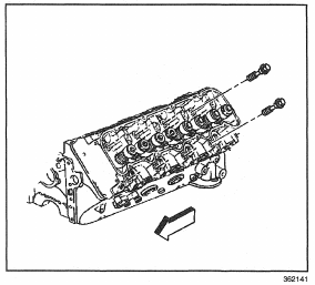
Important: Use a rubber band to hold the rear cylinder head bolt to the cylinder head (passenger side cylinder head only). Due to the clearances, the bolt must be installed at this time.
Notice: Refer to Fastener Notice in Caution and Notices.
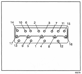
5. Install the cylinder head bolts and tighten in sequence in four passes.
Tighten
5.1. Tighten the bolts to 25 N-m (20 Ib ft).
5.2. Tighten the bolts to 75 N-m (55 Ib ft).
5.3. Retighten the bolts to 75 N-m (55 Ib ft).
5.4. In sequence, tighten all bolts an additional 90 to 100 degrees (1/4 + turn).
6. Install the valve rocker arm , shaft, and the push rods in the cylinder head. Refer to Valve Rocker Arm, Shaft, and Push Rod Replacement.
7. Install the valve rocker arm covers to the cylinder head. Refer to Valve Rocker Arm Cover Replacement.
8. Install the thermostat housing and the bypass hose to the cylinder heads and the engine block. Refer to Thermostat Housing Crossover Replacement in Engine Cooling.
9. Install the ground strap to the right rear cylinder head.
10. Install the left accessory bracket to the cylinder head (if servicing the left cylinder head). Refer to Accessory Brackets Replacement (Left Side)
11. Install the right accessory bracket to the cylinder head (if servicing the right cylinder head). Refer to Accessory Brackets Replacement (Right Side).
12. Connect the vacuum line from the vacuum pump.
13. Install the lower radiator shroud to the radiator.
Refer to Fan Shroud Replacement (Lower) in Engine Cooling.
14. Install the engine cooling fan to the water pump pulley. Refer to Fan Clutch Replacement (5.0L, 5.7L and 6.5L) in Engine Cooling.
Important: Cover the opening from the lower intake manifold to the upper intake manifold, as to not allow foreign material to fall in.
15. Install the lower intake manifold (L 6 5 shown ) to the cylinder heads. Refer to Intake Manifold Replacement (Lower).
16. Install the fuel filter/water seperator to the cylinder head.
Important: Cover the turbo charger mounting surface so as to not allow any foreign material to fall into exhaust manifold or cylinder head.
17. Install the right exhaust manifold to the cylinder head (if the right cylinder head is being serviced).
Refer to Exhaust Manifold Replacement (Right Side).
18. Install the left exhaust manifold to the cylinder head (if the left cylinder head is being serviced).
Refer to Exhaust Manifold Replacement (Left Side).
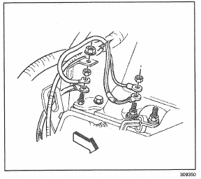
19. Install the glow plugs and the shields to the cylinder head (right side shown).
20. Install the upper intake manifold to the lower intake manifold. Refer to Intake Manifold Replacement (Upper).
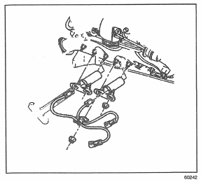
21. Install the engine wiring harness if necessary .
22. Install the turbo charger assembly to the exhaust manifold. Refer to Turbocharger Replacement.
23. Install the transmission oil level indicator and tube.
24. Raise the vehicle.
25. Install the exhaust cross over pipe to the exhaust manifolds. Refer to Exhaust Crossover Pipe Replacement (Diesel) in Engine Exhaust.
26. Lower the vehicle.
27. Install the drive belt on the pulleys. Refer to Drive Belt Replacement (6.5L Drive Belt).
28. Install the upper fan shroud to the radiator. Refer to Fan Shroud Replacement (Upper) in Engine Cooling.
29. Install the engine cover to the upper intake manifold.
30. Refill the cooling system. Refer to Draining and Filling Cooling System in Engine Cooling.
31. Connect both the battery negative cables to the batteries. Refer to Battery Cable in Engine Electrical.