Important: Rotate the engine until the mark on the crank shaft balancer is at the 2 o ’clock position.
Rotate the crank shaft counter clock wise 88 mm (3 1/2 inch), aligning the crank shaft balancer mark with the first lower water pump bolt, about 12:30.
This will position the engine so that no valves are close to the piston crown.
1. Disconnect both the battery negative cables from the batteries. Refer to Battery Cable in Engine Electrical.
2. Remove the valve rocker arm cover from the cylinder head. Refer to Valve Rocker Arm Cover Replacement.
Notice: All valve train components must be reassembled in the exact order and position from which they were removed.
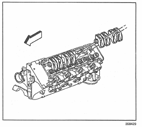
3. Remove the valve rocker arm shaft bolts from the cylinder head.
4. Remove the valve rocker arm shaft with the valve rocker arm.

Important: The push rods must be installed in the original direction as disassembly . This is because the push rods have different degrees of hardness at each end . A paint stripe identifies the upper end of the push rod. If the paint stripe is not visible, mark the push rod on the upper end as the push rods are removed.
5. Remove the push rods from the engine block.
6. Remove the valve rocker arms from the cylinder head.
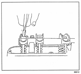
7. Insert a screw driver into the valve rocker arm shaft bore and break off the end of the nylon valve rocker arm retainers.

8. Remove the valve rocker arm retainers with a pair of pliers.
9. Slide the valve rocker arms from the rocker arm shaft.
10. Inspect each of the valve train components. Refer to Valve Rocker Arm and Shaft Clean and Inspect.