|
Make-Up Tank Oil Level – Low
|

Overview
| CODE | REASON | EFFECT |
| Fault Code: 219 PID: FMI: LAMP: Red SRT: |
Make-Up Tank Oil Level – Low. This fault code is displayed to indicate that the make-up oil tank oil is below specified levels. |
The Centinel™ system will not operate. |
|
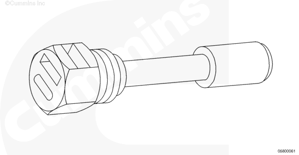
Make-Up Tank Oil Level Low Sensor |
 |
;)
;)
Circuit Description
The make-up tank oil level low sensor monitors the oil level in the make-up oil tank and reports to the Centinel™ control module when the oil drops below the specified level.
Component Location
The make-up tank oil level low sensor is located on the lower portion of the front of the Centinel™ system make-up oil tank.
Shop Talk
Verify that the make-up tank has the appropriate level of oil.
Cautions and Warnings
 CAUTION CAUTION To avoid pin and harness damage, use the following test leads when taking measurements: |
|
CAUTION The component can be damaged internally if dropped. |
|
CAUTION To avoid damaging a new Centinel™ control module, all other active fault codes must be investigated prior to replacing the Centinel™ control module. |
|
CAUTION To avoid pin and harness damage, use the following test leads when taking measurements: |
Troubleshooting Steps
| STEPS | SPECIFICATIONS | |
|---|---|---|
| STEP 1. | Check the make-up tank oil level low sensor. | |
| STEP 1A. Inspect the make-up tank oil level low sensor and Centinel™ harness connectors. |
No damaged pins | |
| STEP 1B. Check the make-up tank oil level low sensor for an open. | Less than 100 ohms | |
| STEP 2. | Check the Centinel™ harness. | |
| STEP 2A. Inspect the Centinel™ harness and the Centinel™ control module connectors. | No damaged pins | |
| STEP 2B. Check for an open circuit. | Less than 10 ohms | |
| STEP 2C. Check for a short circuit from pin to pin. | More than 1k ohms | |
| STEP 3. | Clear the fault codes. | |
| STEP 3A. Disable the fault code. | Fault Code 219 inactive | |
Guided Step 1 – Check the make-up tank oil level low sensor.
| Guided Step 1A – Inspect the make-up tank oil level low sensor and the Centinel™ harness connector. | |
|---|---|
Conditions
Action
For general inspection techniques, refer to Component Connector and Pin Inspection, Procedure 019-361. |
|
| OK | NOT OK |
|
No damaged pins |
Repair the damaged pins Repair or replace the Centinel™ harness or the make-up tank oil level low sensor, whichever has damaged pins. |
| Guided Step 1B – Check the make-up tank oil level low sensor for an open. | |
|---|---|
Conditions
Action
Refer to the wiring diagram for connector pin identification. For general resistance measurement techniques, refer to the Resistance Measurements Using a Multimeter and Wiring Diagram, Procedure 019-360. |
|
| OK | NOT OK |
|
Less than 100 ohms |
Replace the make-up tank oil level low sensor Refer to Procedure 019-056. |
Guided Step 2 – Check the Centinel™ wiring harness.
|
CAUTION To avoid damaging a new Centinel™ control module, all other active fault codes must be investigated prior to replacing the Centinel™ control module. |
| Guided Step 2A – Inspect the Centinel™ wiring harness and Centinel™ control module connectors. | |
|---|---|
Conditions
Action
For general inspection techniques, refer to Component Connector and Pin Inspection, Procedure 019-361. |
|
| OK | NOT OK |
|
No damaged pins |
Repair the damaged pins |
|
CAUTION To avoid pin and harness damage, use the following test leads when taking measurements: |
| Guided Step 2B – Check for an open circuit. | |
|---|---|
Conditions
Action
Refer to the wiring diagram for connector pin identification. For general resistance measurement techniques, refer to the Resistance Measurements Using a Multimeter and Wiring Diagram, Procedure 019-360. |
|
| OK | NOT OK |
|
Less than 10 ohms |
Replace the Centinel™ wiring harness Refer to Procedure 019-131. |
|
CAUTION To avoid pin and harness damage, use the following test leads when taking measurements: |
| Guided Step 2C – Check for a short circuit from pin to pin. | |
|---|---|
Conditions
Action
Refer to the wiring diagram for connector pin identification. For general resistance measurement techniques, refer to the Resistance Measurements Using a Multimeter and Wiring Diagram, Procedure 019-360. |
|
| OK | NOT OK |
|
More than 1k ohms |
Replace the Centinel™ wiring harness Refer to Procedure 019-131. |
Guided Step 3 – Clear the fault codes.
| Guided Step 3A – Disable the fault. | |
|---|---|
Conditions
Action
|
|
| OK | NOT OK |
|
Fault Code 219 inactive |
Return to troubleshooting steps or contact your local Cummins Authorized Repair Location if all the steps have been completed and checked again. |