Centinel System – Repair Manual – 014-999   Engine Testing – Overview

General Information

TOC

This section outlines engine testing and engine run-in recommendations for Signature engines. All engines must be run in after a rebuild or a repair involving the replacement of one or more piston ring sets, cylinder liners, or pistons.

NOTE: Incorrect or insufficient break-in of the piston rings will lead to early oil consumption or high-blowby complaints. Adherence to these run-in guidelines will allow the full durability of new pistons, liners, and rings to be realized.

Before running the engine, make sure the engine is filled with the proper coolant. Also, make sure the lubricating oil system is filled and primed.

 
SMALL | MEDIUM | LARGE

In-Service Run-In:

The following in-service run-in guidelines are recommended for Signature engines after a repair involving replacement of one or more of the piston ring sets, cylinder liners, or pistons where engine or an engine dynamometer and/or chassis dynamometer run-in can not be performed.

The majority of heavy-duty diesel applications will provide sufficient run-in under normal loaded operations. However, light-load/high-rpm operation must be avoided during the run-in period.

Engine Dynamometer Run-In:

This is the preferred method of run-in for engines that have been rebuilt out of chassis. It is neither practical nor recommended that an engine be removed from the application to conduct the run in after a rebuild or cylinder repair has been performed in-chassis. There is no requirement, nor is it recommended, for an engine that has been run-in and tested on an engine dynamometer to be run in again after it has been reinstalled in the vehicle or equipment.

Chassis Dynamometer, Portable Dynamometer, or Load Bank Run-In:

When it is not possible to load an engine immediately after rebuild or repair (example: On-highway tractor that must be “bobtailed” for delivery, a standby generator or fire pump that can not be operated because of customer restrictions, a fire truck that can not be loaded with the water pump, etc.), the engine must be run in on a chassis dynamometer, portable dynamometer, or load bank following the recommendations outlined in the attached procedures.

Fuel Flow Measurement on Engine or Chassis Dynamometer

TOC

Accurate fuel flow measurement is important for evaluation of engine performance and troubleshooting on an engine or chassis dynamometer. The only way an accurate fuel flow measurement can be obtained is through proper use of available equipment. Below is a description of the fuel measuring device, available from Cummins Engine Company, along with installation and operation recommendations. The fuel measuring device, Part No. 3376375, can be used with either a chassis or engine dynamometer.

Installation:

When installing the fuel measuring device, it is important to reduce the amount of air that can be introduced into the system when the device is not in use. Therefore, the plumbing used must include nonrestrictive shutoff valves, such as ballcock valves, to contain fuel in the device after each use. Additional installation considerations are:

  • The fuel measuring device, Part No. 3376375, must be mounted vertically to maintain accuracy and proper operation.
  • A separate fuel supply for use on the dynamometer is recommended. All fuel used in the measuring device must be clean for consistent operation.
  • Care must be taken to reduce fuel line restriction to and from the engine. Minimum recommended hose size is No. 10 for the engine fuel inlet and No. 8 for the engine fuel drain. The length of either hose must not exceed 15 feet.
  • For accurate fuel consumption or flow measurement while testing on a chassis dynamometer, it is recommended to use a fuel cooler to maintain inlet temperature to the fuel gear at 49°C [120°F] or below.
 
SMALL | MEDIUM | LARGE

SMALL | MEDIUM | LARGE

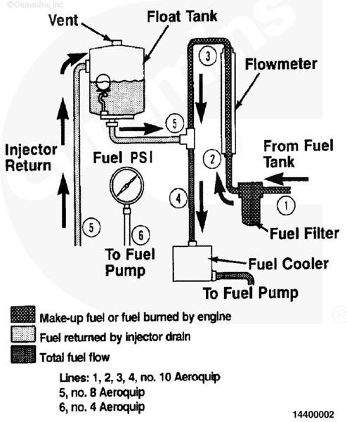
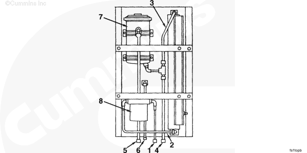
Operation:

This is a schematic of the fuel measuring device, Part No. 3376375. The device consists of the following components:

  • Fuel Filter
  • Flowmeter
  • Float Tank
  • Fuel Rail Pressure Gauge
  • Fuel cooler is not a part of fuel measuring device, Part No. 3376375; however, it must be used when conducting a test with the flowmeter.

SMALL | MEDIUM | LARGE

The fuel measuring device recirculates return fuel to the engine fuel inlet by routing the return fuel to the topside of the float tank. The fuel is deaerated as it passes through the baffling in the float tank. A ball float valve at the bottom of the float tank maintains an adequate volume in the tank for deaeration. The fuel is then returned to the engine fuel inlet. Refer to the sketch for fuel line connection points on the fuel measuring device.

  1. Fuel supply from tank
  2. Fuel flow to fuel meter
  3. Fuel flow from fuel meter
  4. Fuel flow to fuel cooler
  5. Injector return fuel
  6. Fuel rail pressure.

NOTE: The fuel supply tank must be below the level of the fuel measuring device to prevent overflow of the float tank. If an overhead fuel supply tank is used, a float-controlled reservoir must be installed between the fuel supply tank and the fuel measuring device, and below the level of the device.

SMALL | MEDIUM | LARGE

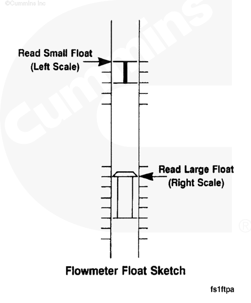
The fuel measuring device is installed in series between the fuel supply tank and the engine fuel inlet. The quantity of fuel being drawn through the flowmeter is known as makeup fuel or the amount of fuel being burned by the engine.

The flowmeter is graduated to read fuel flow in pounds per hour. The flowmeter contains two floats with respective scales on either side of the flowmeter. The small float is used to measure lower flows and must be read on the left scale, as shown. The larger float is for measuring higher flows and must be read on the right scale.

To obtain an accurate fuel rate measurement, the flowmeter reading must be corrected based on the fuel temperature. There is a fuel temperature gauge on the front panel of the fuel measuring device. The gauge is graduated in percent of error by which the reading requires correction. By way of illustration, the fuel of an engine reads 125 lb/hr on the flowmeter, and the temperature gauge reads +2 percent; the corrected fuel flow rate will be 125 plus 2 percent, or 127.5 lb/hr.

Last Modified:  22-Jul-2002