Centinel System – Repair Manual – 001-014   Connecting Rod

View Related Topic


Preparatory Steps

TOC

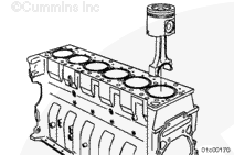
NOTE: The piston and connecting rod
must be removed as an assembly on Signature, ISX, and QSX15 engines.

SMALL | MEDIUM | LARGE

Clean and Inspect for Reuse

TOC

 CAUTION 

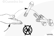
Prevent damage to the capscrews. Nicks in the body of the capscrew can cause an area of stress that can fail during engine operation. Damage to the threads will cause torque values to be incorrect and will damage the mating parts.
 
SMALL | MEDIUM | LARGE


 WARNING 

When using a steam cleaner, wear safety glasses or a face shield, as well as protective clothing. Hot steam can cause serious injury.
 WARNING 
When using solvents, acids, or alkaline materials for cleaning, follow manufacturer’s recommendations for use. Wear goggles and protective clothing to reduce the possibility of personal injury.
 WARNING 

Wear appropriate eye and face protection when using compressed air. Flying debris and dirt can cause personal injury.

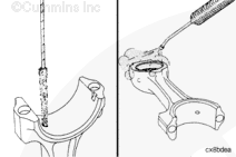
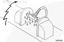
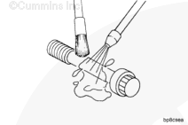
Use solvent or steam to clean the capscrews, connecting rod, and connecting rod cap.

Dry with compressed air.

Use a soft bristle brush to clean the oil drilling.

SMALL | MEDIUM | LARGE


 CAUTION 

Repair of rolled threads by use of a thread die is not recommended. The die can create a sharp corner on the minor diameter (root) of the threads. This sharp corner can cause an area of increased stress.

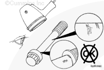
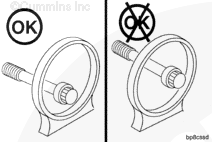
Inspect the capscrews for the following:

  • Damaged threads
  • Rust or corrosion-caused pitting
  • Nicks, bent, stretched, or galled.

The capscrew
must be replaced if it has any of the listed damages.

SMALL | MEDIUM | LARGE


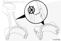
Inspect the connecting rod and connecting rod cap for damage.

Replace the connecting rod if the I-beam or connecting rod cap is damaged.

SMALL | MEDIUM | LARGE


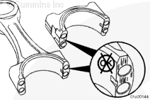
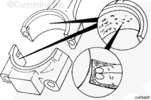
Inspect the connecting rod and connecting rod cap for fretting damage on the mating surfaces.

The connecting rod and connecting rod cap
must be replaced as an assembly if fretting damage is visible on either piece.

SMALL | MEDIUM | LARGE


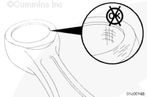
Check the bearing surface for nicks or burrs.

If it is
not possible to remove any nicks or burrs with a fine emery cloth, the connecting rod
must be replaced.

SMALL | MEDIUM | LARGE


Inspect the rod pin bushing for damage.

Replace any piston pin bushing that has evidence of scoring, galling, or scuffing.

Replace any bushing that has turned in the bore.

Special tools and precision machining are required to replace bushings. If Cummins approved tools and procedures are
not available, the connecting rod
must be replaced.

SMALL | MEDIUM | LARGE


 CAUTION 

The connecting rod cap alpha characters must match the alpha characters on the connecting rod and must be installed with the characters aligned to prevent damage to the connecting rods and crankshaft.
 CAUTION 

Use a vise with brass jaws to hold the connecting rod. Notches, scratches, or dents in the I-beam area can cause engine failure.

Place the connecting rod into a vise with brass jaws. Support the connecting rod at the large bearing end to avoid I-beam damage.

Install the connecting rod cap onto the connecting rod.

Lubricate the threads of the capscrews with clean engine oil.

Thread the capscrews into the connecting rod and hand tighten.

The procedure for tightening used capscrews is different than the procedure for tightening new capscrews.

For used connecting rod capscrews:

Tighten Capscrews in Numerical Sequence

  Step 2 70 ± 6 n.m   [52 ± 4 ft-lb]
  Step 3 Rotate capscrews in numerical sequence 60 ± 5 degrees

For new connecting rod capscrews:

Tighten Capscrews in Numerical Sequence

  Step 2 40 ± 6 n.m   [29 ± 4 ft-lb]
  Step 3 Loosen capscrews in numerical sequence
  Step 4 70 ± 6 n.m   [52 ± 4 ft-lb]
  Step 5 Rotate capscrews in numerical sequence 60 ± 5 degrees

SMALL | MEDIUM | LARGE


Measure the connecting rod crankshaft bore inside diameter with a bore dial indicator.

Connecting Rod Crankshaft Bore Inside Diameter
mm in
98.801 MIN 3.890
98.839 MAX 3.891

If the connecting rod crankshaft bore inside diameter is
not within specifications, the connecting rod
must be replaced.

SMALL | MEDIUM | LARGE


Measure the connecting rod piston pin bushing inside diameter.

Connecting Rod Piston Pin Bushing Inside Diameter
mm in
63.55 MIN 2.502
63.57 MAX 2.503

If the connecting rod piston pin bushing inside diameter is
not within specifications, the connecting rod
must be replaced.

SMALL | MEDIUM | LARGE
   

Bend and Twist Inspect

TOC

Calibration Procedure


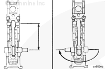
A connecting rod of known length, bend, and twist is called the reference connecting rod, and is required to calibrate the fixture.

A new connecting rod, for which the distance from the center of the crankshaft bore to the center of the piston pin bore (rod length) is known, can also be used.

 
SMALL | MEDIUM | LARGE


The connecting rod cap
must be installed and tightened to the correct specifications or the calibration will be incorrect.

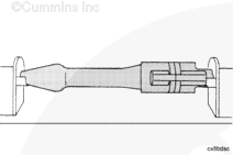
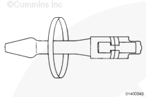
Install the appropriate connecting rod checking guide into the reference connecting rod piston pin bore and center the guide.

Install the appropriate connecting rod checking guide into the reference connecting rod crankshaft bore.

Make sure the pin on the guide is down and centered in the connecting rod.

Lock the guide in position by rotating the end of the guide.

SMALL | MEDIUM | LARGE


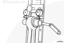
Install the reference connecting rod into the connecting rod checking fixture.

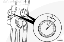
Loosen the knob and move the indicator bracket until both indicators touch the top of the piston pin guide.

Move the bracket toward the guide until the indicator needles have moved approximately 0.25 mm [0.010 in].

Turn the knob to tighten the bracket.

Adjust the indicator needles to zero. Move the connecting rod in and out to confirm the zero setting.

SMALL | MEDIUM | LARGE


Remove the reference connecting rod from the fixture.

Rotate the connecting rod 180 degrees horizontally and install it into the fixture.

SMALL | MEDIUM | LARGE


Be sure the indicators are at the zero setting.

If the indicator needles do
not return to zero, adjust the indicator so the zero moves ½ of the indicated difference from the needle to the zero established during the previous step.

If the needle is more than 0.10 mm [0.004 in] from the zero established during the previous step, check for dirt or burrs on the connecting rod checking guides and fixture. If the zero is still
not within the specification, check to make sure the reference connecting rod is
not damaged.

Do
not adjust the indicators after this step of the procedure or the measurements will be incorrect.

After completing the calibration of the fixture, remove the reference connecting rod.

SMALL | MEDIUM | LARGE
   

Test


 CAUTION 

To reduce the possibility of engine damage, the connecting rod testing fixture must be calibrated prior to testing the connecting rod.

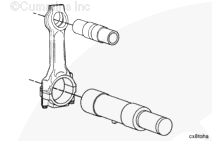
Install the appropriate mandrel in the piston pin end of the connecting rod.

Make sure the locating pin in the mandrel for the crank pin end is touching the connecting rod cap, directly opposite the beam of the connecting rod.

Install the mandrel in the crank pin bore of the master connecting rod.

Tighten the mandrel so it is centered in the bore correctly.

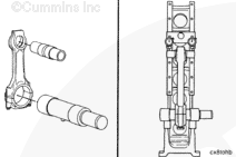
Install the master connecting rod in the testing fixture.

Loosen the knob and move the indicator bracket until both indicators touch the top of the piston pin end mandrel. Move the bracket toward the mandrel until the indicator needles have moved approximately 0.25 mm [0.010 in]. Turn the knob to tighten the bracket.

Adjust the indicator needles to zero. Move the master connecting rod in and out to confirm the zero setting.

Remove the master connecting rod from the fixture.

Rotate the connecting rod 180 degrees horizontally and install it in the checking fixture.

Record the indicator reading. The difference calibrated “0” of the indicator
must be added or subtracted from the known length of the master connecting rod to determine the length of the connecting rod being measured.

Connecting Rod Length
mm in
261.45 MIN 10.293
261.55 MAX 10.297

If the connecting rod length is
not within specifications, the connecting rod
must be replaced.

SMALL | MEDIUM | LARGE


 CAUTION 

Never attempt to straighten a connecting rod with the use of heat or force. The connecting rod can eventually break and cause extensive engine damage.

Record indicator readings.

Remove the connecting rod from the fixture.

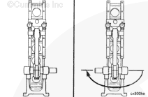
Turn the connecting rod 180 degrees horizontally and install it into the checking fixture.

Compare the indicator readings with those noted in the previous step. The difference between the indicator readings is the amount of bend in the connecting rod.

Maximum Connecting Rod Bend (Bushing Installed)
mm in
0.021 MAX 0.0008

If the connecting rod bend is
not within specification, the connecting rod
must be replaced.

 
SMALL | MEDIUM | LARGE


 CAUTION 

Never attempt to straighten a connecting rod with the use of heat or force. The connecting rod can eventually break and cause extensive engine damage.

Check the fixture and mandrel in the piston pin end for a gap between the two. If there is any twist in the connecting rod, the mandrel will touch
only one side of the fixture.

Hold the end of the mandrel that is touching the fixture firmly against the fixture.

Use a feeler gauge to measure the gap between the mandrel and the fixture. The amount of gap between the mandrel and the fixture is the amount of connecting rod twist.

Maximum Connecting Rod Twist (Bushing Installed)
mm in
0.05 MAX 0.002

If the connecting rod twist is
not within specification, the connecting rod
must be replaced.

SMALL | MEDIUM | LARGE
   

Magnetic Crack Inspect

TOC

This procedure describes the magnetic particle inspection for the connecting rod and connecting rod cap.

Use a magnetic particle testing machine.

The connecting rod and connecting rod cap
must be assembled during this process.

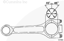
Use the residual method. Apply head shot amperage. Adjust the amperage to 1500 ampere direct current or rectified alternating current.

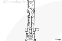
Check for cracks.

The connecting rod
must be replaced if any cracks are visible.

SMALL | MEDIUM | LARGE


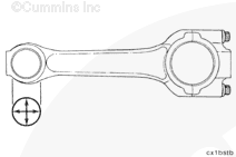
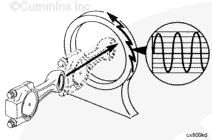
Use the residual method. Apply coil shot amperage.

Amperage (Ampere Turns)
Minimum Maximum
2600 amps direct current 2800 amps direct current

Ampere turn is an electrical current of one ampere flowing through the coil, multiplied by the number of turns in the coil.

SMALL | MEDIUM | LARGE


Check for cracks.

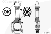
The connecting rod
must be replaced if any indications are visible in the critical (shaded) areas.

SMALL | MEDIUM | LARGE


 WARNING 

When using a steam cleaner, wear safety glasses or a face shield, as well as protective clothing. Hot steam can cause serious injury.
 WARNING 

When using solvents, acids, or alkaline materials for cleaning, follow manufacturer’s recommendations for use. Wear goggles and protective clothing to reduce the possibility of personal injury.
 CAUTION 

The connecting rod must be demagnetized completely and cleaned thoroughly. Any small metal particles will cause engine damage.

Demagnetize the connecting rod.

Use solvent or steam to clean the connecting rod.

SMALL | MEDIUM | LARGE


This procedure describes the magnetic particle inspection for the connecting rod capscrew.

 
SMALL | MEDIUM | LARGE


Use a Magnaflux™ or similar magnetic particle testing machine.

Use the continuous method. Apply a head shot of 300 to 400 amperes direct current or rectified alternating current.

SMALL | MEDIUM | LARGE


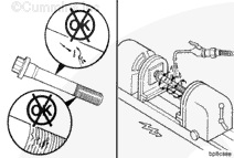
Use an ultraviolet light. Check for indications of cracks.

The magnetic particles tend to form on sharp corners and edges. Do
not mistake these for cracks.

Any indications of cracks are
not acceptable.

SMALL | MEDIUM | LARGE


Prepare the machine for a coil shot.

Make sure the capscrew is near one side of the coil and
not in the center.

Apply 1000 to 1350 ampere-turns.

SMALL | MEDIUM | LARGE


Use an ultraviolet light. Check for indications of cracks.

Any indications of cracks are
not acceptable.

SMALL | MEDIUM | LARGE


 WARNING 

When using solvents, acids or alkaline materials for cleaning, follow the manufacturer’s recommendations for use. Wear goggles and protective clothing to reduce the possibility of personal injury.
 WARNING 

Wear eye and face protection when using compressed air. Flying debris and dirt can cause personal injury.
 CAUTION 

The connecting rod must be demagnetized completely and cleaned thoroughly. Any small metal particles will cause engine damage.

Demagnetize the capscrew thoroughly.

Use solvent to clean the capscrew and dry with compressed air.

SMALL | MEDIUM | LARGE
   

Finishing Steps

TOC

NOTE: The piston and connecting rod
must be installed as an assembly on Signature, ISX, and QSX15 engines.

SMALL | MEDIUM | LARGE
Last Modified:  01-Nov-2007