Do not remove the pressure cap from a hot engine. Wait until the coolant temperature is below 50°C [120°F] before removing the pressure cap. Heated coolant spray or steam can cause personal injury.
WARNING
Coolant is toxic. Keep away from children or pets. If not reused, dispose of in accordance with local environmental regulations.
WARNING
To reduce the possibility of personal injury, avoid direct contact of hot oil with your skin.
WARNING
Some state and federal agencies have determined that used engine oil can be carcinogenic and cause reproductive toxicity. Avoid inhalation of vapors, ingestion, and prolonged contact with used engine oil. If not reused, dispose of in accordance with local environmental regulations.
This component or assembly weighs greater than 23 kg [50 lb]. To prevent serious personal injury, be sure to have assistance or use appropriate lifting equipment to lift this component or assembly.
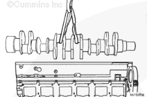
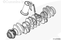
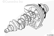
Use a lifting strap that will not damage the crankshaft.
Use a hoist and a sling that to remove the crankshaft.
When using solvents, acids, or alkaline materials for cleaning, follow the manufacturer’s recommendations for use. Wear goggles and protective clothing to reduce the possibility of personal injury.
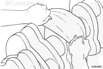
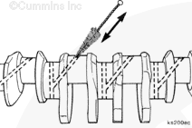
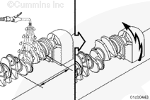
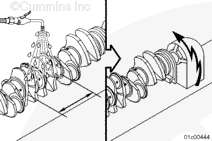
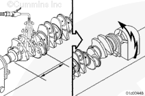
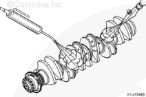
Use a bristle brush and solvent to clean all of the crankshaft oil drillings.
When using solvents, acids, or alkaline materials for cleaning, follow the manufacturer’s recommendations for use. Wear goggles and protective clothing to reduce the possibility of personal injury.
WARNING
Wear appropriate eye and face protection when using compressed air. Flying debris and dirt can cause personal injury.
CAUTION
Do not use a thread chaser to clean the capscrew threads in the crankshaft, severe engine damage can result.
ISX applications use rolled capscrew threads in the capscrew holes of the crankshaft.
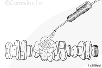
To clean the rolled threads, flush with solvent, and dry with compressed air.
If additional cleaning is required, brush with a nylon bristle brush.
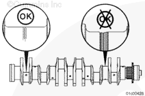
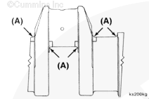
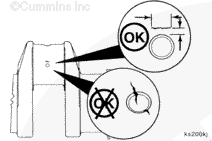
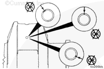
Inspect the crankshaft for dynamic balancing marks. One or more of the crankshaft counterweights will contain a drilled hole or drilled start point indicating that the crankshaft has been balanced.
NOTE: This applies to engines built March 2009 or later only.
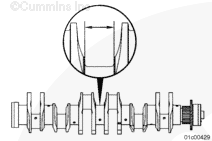
Inspect the threaded capscrew holes for damage.
If the threaded capscrew holes are damaged, the crankshaft must be replaced.
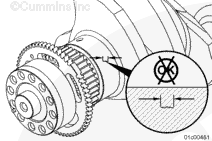
Inspect the crankshaft gear and tone wheel for excessive wear or damage.
If any teeth on the crankshaft gear are missing, chipped, or pitted, the crankshaft gear must be replaced.
If any teeth on the tone wheel are missing, the tone wheel must be replaced.
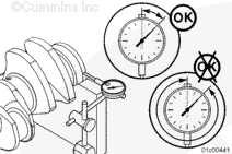
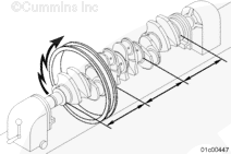
The crankshaft alignment limits are based on total indicator runout. The runout is measured as the crankshaft is turned one revolution while recording the total movement of the dial indicator.
This component or assembly weighs greater than 23 kg [50 lb]. To prevent serious personal injury, be sure to have assistance or use appropriate lifting equipment to lift this component or assembly.
CAUTION
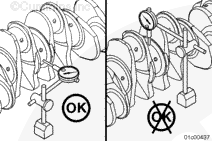
Measuring from the top of the main bearing journal will cause inaccurate alignment measurements because of crankshaft sag.
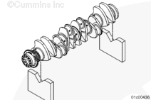
To check the crankshaft full length alignment, support the crankshaft on the number one and number seven main bearing journals.
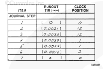
Bearing to bearing runout is defined as the relationship of the total indicator runout of a main bearing journal as it is rotated on a common axis to the total indicator runout of an adjacent journal.
Bearing to bearing runout is often referred to as step runout, adjacent runout or journal to journal runout.
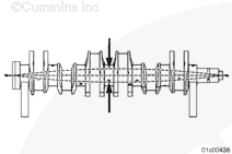
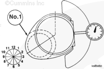
The clock position is defined as the location of the journal at the highest total indicator runout point. Compare its angular relationship with the number one crankshaft pin, as viewed from the front of the crankshaft.
In the illustration, the crankshaft pin is at the 8 o’clock position. This is the clock position of the journal being measured.
This component or assembly weighs greater than 23 kg [50 lb]. To prevent serious personal injury, be sure to have assistance or use appropriate lifting equipment to lift this component or assembly.
CAUTION
Measuring from the top of the main bearing journal will cause inaccurate alignment measurements because of crankshaft sag.
To check the crankshaft full length alignment, support the crankshaft on the number one and number seven main bearing journals.
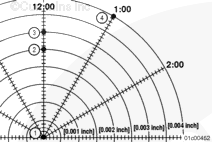
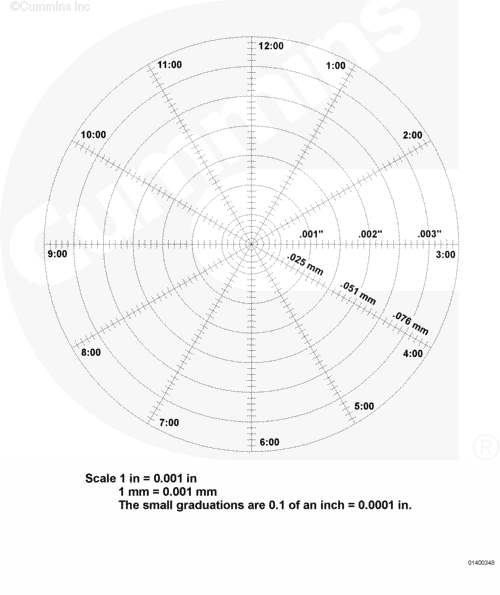
For each journal, plot the total indicator runout value at its clock position on a polar chart.
The end journals, supported by vee blocks, must be plotted at the center of the chart.
The illustration illustrates the plot points.
Journal
Total Indicator Runout
Clock Position
(1)
0
0
(2)
0.002
12
(3)
0.003
12
(4)
0.004
1
Draw a straight line between the plotted points. From journal number one, to journal number two, to journal number three, until all journals are plotted on the chart.
To determine the adjacent journal runout, measure the length of the line from each journal to its corresponding journal point.
In the above table journal number three and number four are 51 mm [2 in]. This represents a runout of 0.051 mm [0.002 in].
Record the adjacent runout for each main bearing journal.
If the alignment between adjacent journals is not within specifications, it can not be repaired by grinding. The crankshaft must be replaced. ISX crankshafts are fully fillet hardened and can not be straightened.
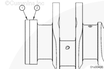
Rear oil seal flange diameter runout measurement:
With the crankshaft supported on the number one and number seven main bearing journals, position a dial indicator 25.4 mm [1.0 in] from the flywheel mounting face of the crankshaft.
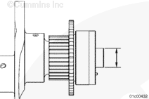
Front oil seal crankshaft adapter diameter runout measurement:
With the crankshaft supported on the number one and number seven main bearing journals, position a dial indicator 25.4 mm [1.0 in] from the balancer mounting face of the crankshaft.
The crankshaft must be tested by the “continuous method”. The entire surface must be wetted with the magnetic bath solution before and during the flow of magnetic current through the crankshaft.
For the head shot (longitudinal magnetization) method, apply the magnetic bath solution to the crankshaft and use 3800 amperes with VDC or rectified VAC to magnetize the crankshaft.
For the coil shot (circumferential magnetization) method, apply the magnetic solution and magnetize the crankshaft in a 51.35 mm [20.249 in] inside coil or equivalent. Use 3,600 to 4,000 ampere-turns with VDC or rectified VAC.
Amepere-turn is the amperage flowing through the coil multiplied by the number of turns in the coil.
Open indications on the crankpin or main bearing journal surfaces that extend closer than 3 mm [0.12 in] to the fillet but do not enter the fillet are acceptable.
Open indications in the longitudinal direction up to 12.5 mm [0.5 in] in length, but not closer than 3 mm [0.12 in] to the oil hole chamfer are acceptable.
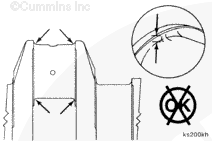
Open indications that enter the oil hole chamfer or intersect the oil hole at 45 degrees ± 10 degrees are not acceptable.
Subsurface indications can not be seen with the eye after magnetic particles have been removed. These are indications of open areas or foreign objects below the surface.
This component or assembly weighs greater than 23 kg [50 lb]. To prevent serious personal injury, be sure to have assistance or use appropriate lifting equipment to lift this component or assembly.
CAUTION
Use a lifting strap that will not damage the crankshaft. Do not drop the crankshaft on the bearings.
Hello, I'm Jack, a diesel engine fan and a blogger. I write about how to fix and improve diesel engines, from cars to trucks to generators. I also review the newest models and innovations in the diesel market. If you are interested in learning more about diesel engines, check out my blog and leave your feedback.
View all posts by Jack


 WARNING

 CAUTION















;)
;)
;)
;)
;)
;)
;)
;)
;)
;)
;)
;)
;)
;)
;)
;)
;)
;)
;)
;)
;)
;)
;)
;)
;)
;)
;)
;)
;)
;)
;)
;)
;)
;)
;)
;)
;)
;)
;)
;)
;)
;)
;)
;)
;)
;)
;)
;)
;)
;)
;)
;)
;)
;)
;)
;)
;)
;)
;)
;)
;)
;)
;)
;)
;)
;)
;)
;)
;)
;)
;)
;)
;)
;)
;)
;)
;)
;)
;)
;)
;)
;)
;)
;)
;)
;)
;)
;)